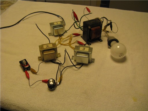
A magnetic amplifier is a circuit that uses changes in core saturation of an inductor to bring about amplification. A small amount of DC current change from the 9 volt battery and a 1k pot can cause a large amount of AC current change through a car headlight.
The purpose of this article is to de-mystify the esoteric magnetic amplifier and to describe how to build simple homemade magnetic amplifiers using common 12 volt transformers.
This is the real deal; gain from a transformer, a component that is normally considered to be passive. In most applications, transformers are merely used to step AC voltages up or down without actually amplifying. A common transformer in a magnetic amplifier circuit however, can actually exhibit gain just like a transistor or tube. The magnetic amplifier is only different from a transistor amplifier in that a small amount of DC current controls a large amount of AC current in the output instead of controlling a large amount of DC current in the output.
To evaluate the amount of gain in my magnetic amplifier circuits, I compared the change of input power with the change of output power dissipated by the output load. In other words, I multiplied the change of output voltage across the load times the change of current through the load. I then divided this by the change of input voltage times the change of input current.
Let's say you want to run an auto headlamp on 12V AC and make a dimmer circuit that uses a normal sized 1K ohm pot. The pot would just burn up if it were put in series with the auto headlight so, some kind of circuit with gain is necessary in order to get adequate control from the 1k pot.
For a project like this, the use of triacs or power transistors generally come to mind but, the lesser known magnetic amplifier can do the same job without using any triacs, transistors or tubes.
There are some good articles online about magnetic amplifier theory. Two of the best are: The Transformer Book by Lee Reuben and Magnetic Amplifiers by Mali. They can be found on google. Most of these articles however, describe mag amps in theoretical terms. They can easily lead one to think that special cores and transformers would be necessary in order to to actually build a magnetic amplifier. Nothing could be farther from the truth.
From my own experiments, I have found that normal everyday transformers including 12V filament transformers sold by Radio Shack, work impressively well for making magnetic amplifiers. The use of three leg and other special mag amp transformer cores are also described in mag amp articles but I have just experimented with standard transformers because of their easy availability. I also get great satisfaction from making exotic processes work just from using commonly available materials.
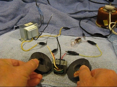
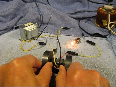
To begin, I would like to first show a simple experiment that demonstrates how saturating a magnetic core can lower inductance and allow more AC current to flow through a lamp.
The lamp glows brighter when the magnets are near the transformer. The magnetic field saturates the core, lowering the inductive reactance in series with the lamp.
Also, shorting the unused winding will cause the lamp to light to full brilliance. Because of this we can not use this circuit yet as a magnetic amplifier. Explanation will follow shortly.
Instead of using magnets, a DC voltage applied to another winding can also cause the core to saturate. This is the basis of a magnetic amplifier circuit.
To understand how a Magnetic Amplifier can amplify, imagine a 12 V filament transformer that has a primary 120 V winding and a secondary 12 V winding. The secondary 12 V winding is connected in series with 12 VAC and a lamp. The primary winding has roughly ten times as many turns as the secondary. By running a small DC control current through the 120 V primary winding, amplification is possible because this small current can generate enough ampere turns to saturate the core. This lowers the inductive reactance of the 12V secondary, allowing more AC current to flow through the lamp making it brighter. A small change in DC current applied to the 120 V primary winding can cause a much larger change in AC current flowing through the 12 V secondary winding. This can be stated another way. A small change in power dissipated across the 120V primary can cause a much larger change in power dissipated across a load connected to the 12 V secondary.
This circuit configuration however, presents some problems that need to be addressed. When using a single transformer, high voltage AC will appear, through transformer action, across the 120 V control winding. This high voltage can burn up a potentiometer or whatever is connected to this 120 V winding. We don't want to have this high voltage AC coming out of the magnetic amplifier input.
There is also the problem that the lamp will light to full brilliance if the 120 V control winding is simply shorted. With no input applied to the amplifier, it should not make any difference whether the input is open or shorted.
A solution to this is to use two transformers. The output AC current can be run through the 12 V windings of both transformers either in series or parallel. The 120 V input windings can be connected in series so that the AC voltages induced in them from transformer action, are out of phase and cancel. This allows small DC control voltages to be applied to the two 120 V windings without interaction with high voltage AC. Since each transformer core can saturate, independently of the other, the DC control windings have full core saturation effect even though they are connected out of phase.
It is easy to tell when the two input control windings are phased properly by shorting the input. If the phase is wrong, the lamp will light to full brilliance. If the phase is correct, the lamp condition will show little or no change.
With this type of Magnetic Amplifier circuit, the lamp will normally be dim or off when zero control voltage is applied. DC control voltages of plus or minus polarity, when applied to the input, will cause the lamp to get brighter.
The circle with the sine wave symbol in the center is an AC power supply. In the case of the circuits described here, it is typically a 12v transformer powered from a 120 V 60 HZ outlet.
Magnetic amplifiers seem to be best suited for driving low impedance loads in their output. The 12 V car headlight is a typical example. By connecting a step up transformer to the output of one of my 12 V transformer mag amps, I was able to control a 120 V 60 Watt lamp.

I was impressed to observe typical power gains of 15 to 25 using the two transformer circuit but, after adding a couple of silicon rectifier diodes to the circuit as shown above, I started to observe amazing power gains of well over 1000!! The diode circuits that I have made do not put out as much power under my experimental conditions but the relative amount of input control current change necessary to control the output is a very tiny fraction of what is required when no diodes are in the circuit.
Why is this so? The diodes cause pulsating DC current to flow through the coils. This pulsating DC current has a tendency to bias the coils toward saturation just as though it were applied to the input. It is easy to see why this kind of circuit is called a self biasing magnetic amplifier. This bias effect also appears as positive feedback. Positive feedback in any kind of amplifier usually translates into an increase in amplification. With more positive feedback, an amplifier can become unstable or capable of acting as a bistable flip flop. I have also succeeded in making some bistable magnetic amp circuits.
Magnetic Amplifier articles also explain that by the use of diodes, the core is prevented from being saturated in both the negative and positive direction. This raises efficiency by eliminating hysteresis losses.
With this type of Magnetic Amplifier circuit, the lamp will usually be lit to some degree when zero control voltage is applied. DC control voltages applied in one polarity to the input will cause the lamp to get brighter while DC control voltages applied in the opposite polarity will cause the lamp to get dimmer.
Some mag amp articles convey a "Stuff Shirt" attitude that a circuit must have diodes in order to be called a Magnetic Amplifier and that a circuit without diodes is called a Saturable Reactor. A circuit without diodes may have a power gain of just 15 but it is still impressive and can certainly amplify . Why should it make any difference whether a circuit has a gain of 15 or 1500 in order for it to be called an amplifier?
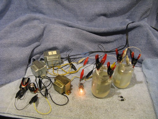
I was curious to see if homemade borax rectifiers (in the two jars) could be used instead of modern silicon rectifiers to increase the gain of the mag amp circuit. The answer is: They can indeed.
Two silicon diodes can be seen sitting in the foreground unconnected.
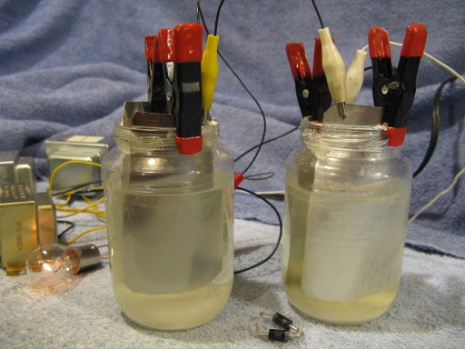
These borax rectifiers are crude as compared to modern silicon diodes but I was still able to observe an amazing power gain of around 450 while using them in the mag amp circuit.
Homemade Magnetic Audio Amplifier.