|
|
|
 |


|
|||||||
| Renewable Energy Discussion on various alternative energy, renewable energy, & free energy technologies. Also any discussion about the environment, global warming, and other related topics are welcome here. |
|
|
BEDINI
RPX FREE
BOOK OR VIDEO OFFER Available here: Bedini RPX Sideband Generator |
 |
|
|
Thread Tools

|
|
#1
 12-10-2014, 04:48 AM
|
|||
|
|||
 Tesla's Special Tri-Metal Generator
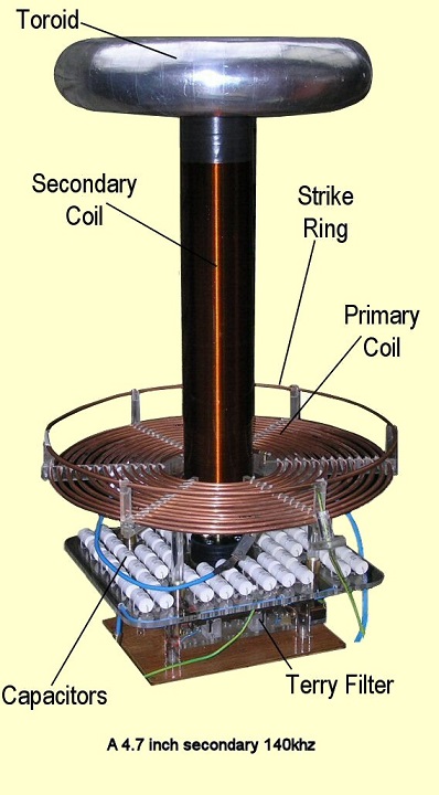
According to William Lyne in his book, Pentagon Aliens, Tesla had a generator that the Nazi's used during WWII in their electro-U boats having a range of 30,000 miles. The generator used the three metals of: aluminum, copper and iron. For every 200 pounds of iron attached to the device (in addition to any iron inside of any coil windings), one horsepower was added to the generator's output. The electro-mechanical watt hour meter of a bygone era (for some of us) is an extremely scaled down version of Tesla's Special Generator to the point of mediocrity.
So,... Anyone have any ideas to share? Mr. Lyne doesn't give much information more than this towards the back of his book, but he does give pictures and some insightful speculation on how it might have worked. One embodiment of his employs the use of compressed air to drive a reciprocating piston which oscillates no more than a sixteenth of an inch. Also, its frequency of oscillations must be in resonance with the cavity surrounding the generator. Mr. Lyne speculates that the huge hull of Germany's U-boats would have added a lot of horsepower if connected to this device. Since I don't have any background in electrical bench testing, or even theory, my best guess is to stumble along holding onto wishful thinking driven by the notion that - if its true that 550 of Tesla's patents, out of a total of 700 - are highly classified *top secret*, and that this one patent of Tesla's is just one among those that have been squirreled away from us, then I feel that it belongs to us and not to a privileged few. So, I'm game to speculate on the notion that maybe we can slowly figure this mystery out.
__________________

|
| Sponsored Links | ||
|
|
|
#2
12-10-2014, 05:00 AM
|
|||
|
|||
|
I might as well add that a friend of mine, an electrician, had the good fortune of personally knowing a coworker who demonstrated a successful replication of this type of device several years ago no larger than a spiral bound notebook for two of its dimensions which ran a medium sized electric motor. It was taken away and the demonstration was abruptly terminated when the inventor started having misgivings for exhibiting his device and it was never discussed nor demonstrated ever again except at a dinner in which my friend hosted this inventor. At this dinner, the inventor shared only one fact of his device, that it was made of the three metals: copper, aluminum and iron. So, I can claim knowing twice removed of the validity of Mr. Lyne's story in addition to the story - quoted in Pentagon Aliens - of a Mr. Dort who was the son of a man who worked with Tesla sharing this knowledge with the Nazis for their electro-U boats.
__________________
Last edited by Vinyasi; 12-10-2014 at 05:02 AM. Reason: grammar and clarity
|
|
#3
12-10-2014, 05:43 PM
|
|||
|
|||
|
Quote:
Overview of Single Phase Induction Type Energy Meter | EEP It should be possible to work out what is going on. someone said that it had physics in common with the unipolar generator.
__________________
|
|
#4
12-10-2014, 07:08 PM
|
|||
|
|||
|
Quote:
Although I thought I had experimented enough, and because Mr. Lyne said that any make and model of the electro-mechanical watt hour meter will do the job, I stopped experimenting because I was failing to produce results, namely: reaching center of load wherein the aluminum disk stops spinning and hums. According to the Electrical Meterman's Handbook from 1912, this occurs whenever the amperage and voltage are out of phase by 60 degrees (possibly with the current still retaining its leading position ahead of voltage instead of swapped?). Mr. Lyne said there was only a few requirements: wire the meter backwards such that the line entering from the power source is connected to the load terminals on the meter, and the load wire is connected to the line terminals. The other requirement is to increase the load. A patent from the 1930s admitted that it was known back then that the aluminum disk slows down around 300% to 400% of rated load for the meter. And this occurs, according to Mr. Lyne, whenever the increasing load is approaching the meter's center of load. The disk will speed up, slow down, stop and hum, and then slowly (at first) speed up in reverse direction as the load is increased. But only if the terminals on the meter are reverse connected to line and load. Various meter handbooks speak of the commonality of meter disks reversing direction merely from swapping terminal connections. This implies that the disk is already reverse spinning (when the terminal connections are swapped) before center of load is reached. So that, once center of load is surpassed with increasing load, then the disk will resume in a spin opposite to its former direction - which will be standardly normal, left to right on the dial! I loaded up a General Electric I-10 meter from 1910, General Electric Type I-10 ...rated at 5-10 amps, to around 48 amps and no sign of any reduction in speed of disk - let alone humming or reversing. I tried both forward and backwards terminal connections. Plus, I tried various loads: inductive and non-inductive. I was afraid of taking the amperage any higher for fear of overheating the house wiring in the walls. Maybe I'll try again with the model which you have suggested.
__________________
|
|
#5
12-11-2014, 02:13 AM
|
||||
|
||||
|
Based on info in Lyne's book I bought 4 regular house electric meters (mechanical - not the new electronic type) a couple years ago. I played around with them a little and was trying for the effect he said he saw with 2 meters hooked together in some way that resulted in the meter going backwards on the house. I had some trouble figuring out how the meters were normally wired up if I recall despite doing all my own house wiring including installing the main 200 amp meter socket and panel. I had always intended to write Lyne to ask his help on this but it got lost in the shuffle of a hundred other things to do. I still have the 4 meters. Might play around with them some more but it would help if there was a schematic on how to set them up. I don't actually recall him saying to hook ONE up in reverse by itself. Was that in his book?
__________________
There is no important work, there are only a series of moments to demonstrate your mastery and impeccability. Quote from Almine
|
|
#6
12-11-2014, 02:53 AM
|
|||
|
|||
|
Reverse wiring of the watt-hour meter...
No. Reverse wiring was not in his book. What he said was, "in a peculiar way".
But he was interviewed by a Paul Scarzo and, in that interview, he admits to accidentally hooking them up backwards on two separate branch circuits in one of the apartments in his complex. He also has admitted the backwards requirement, more than once, in emails to me. I did a watt hour meter YouTube series starting off with an excerpt from that interview. Here it is, http://tinyURL.com/tesla-sgen or http://tinyURL.com/teslasgen ...or search for the video series using the search terms: tesla's tri-metal generator
__________________
Last edited by Vinyasi; 01-01-2015 at 05:39 PM. Reason: added a title and a short-cut link
|
|
#7
12-11-2014, 11:08 AM
|
|||
|
|||
|
Aluminium
The first two posts of this thread may be relevant to this topic.
Dirty electrcity
__________________
|
|
#8
12-15-2014, 06:19 PM
|
|||
|
|||
|
Dirty Electricity and the Watt-Hour Meter...
Quote:
In retrospect, I didn't immediately understand until now what you were implying, that aluminum - although functional in the original design of the watt-hour meter - is hampering our ability to measure what is going on: the production of dirty electricity. To play it safe, I've ordered one DE suppressor and will probably order some more in the near future. Despite these hazards, or instead of them, and in order to better understand how Tesla's Special Generator may have operated, I still pursue investigation into how on Earth do these old meters do their thing? I've sometimes wondered if the separation of voltage from current in the watt-hour meter's armature might jeopardize our safe cohabitation with it? But I like to hold out the possibility of utilizing at least some of its principles of operation for some other device. Here is a review I posted at Amazon on Joseph Cater's book, "The Awesome Life Force" regarding the reaction of aluminum to electromagnetic forces placed upon it ... Fantastic text on little known principles of mechanical and electrical engineering..., December 15, 2014
__________________
|
|
#9
12-15-2014, 07:48 PM
|
||||
|
||||
|
Quote:
you can download that book FREE on scribd.com  
__________________
|
|
#10
12-23-2014, 06:25 PM
|
|||
|
|||
|
DC Transformers and Perpetual Motion Holders
I may never figure out how Tesla's Special Tri-Metal Generator works, but in the course of trying to figure out one thing, very often something else miraculously happens...
No one has done the correct experiment (show me if you know where; I want to know) to validate that transformers do indeed respond to a DC current. Paul Babcock did the standard, one half of this experiment when he visited the Science, Energy and Technology Conference of 2013. He had Ed Leedskalnin's Perpetual Motion Holder experiment set up off to the side of the lecture hall. The other half of a DC transformer experiment is to put two diodes in the middle of a double-pole, double throw switch inline with one lead coming off the PMH coil/s and the other lead that goes to the battery during charge. The other lead from the PMH coil/s could go to the light bulb and thence toward the other battery terminal during the charge cycle when these two bare battery leads are not bound together during discharge (which also lights up the light bulb). The light bulb lights up twice: during both charge and discharge. An AC transformer has its primary and secondary coils separated. The DC transformer uses one coil to perform both charge and discharge of its combination straight bar plus horseshoe iron circular core. An AC transformer terminates the first half cycle by electromagnetically breaking its iron core ring every 1/120th of a second (in a 60Hz electrical system) by attempting to recharge the transformer's core with a reverse current. For some reason, the energy which was put into the iron core at the start of the prior 1/120th of a second can't change its auto-pilot, DC habit of zipping around the toroidal core in its one particular DC direction without exiting the core, instead. This makes way for the new energy of reverse polarity to enter the system through the primary coil windings while the secondary coil absorbs some of the exiting energy put in during the prior AC half-cycle. Up until now(?), the only way to duplicate the electrical termination of the first half cycle of an AC transformer within the context of a DC demonstration, was to physically break the circularity of the PMH/DC transformer ring by removing the straight iron (magnetizable) bar at the end of the two legs of the iron (magnetizable) horseshoe. The diodes are to validate, by way of experimentation, that only two out of eight combinations are possible to light up the light bulb twice during both charge and discharge of the horseshoe/bar ring.
Oops... We have /a/ perpetual motion /holder/ sitting under our collective noses within each and every AC transformer...    
__________________
Last edited by Vinyasi; 12-23-2014 at 08:00 PM. Reason: added a schematic and improved grammar and added emphasis...
|
|
#11
12-23-2014, 07:52 PM
|
|||
|
|||
|
PMH and Back EMF
Let's take this surmising one step further...
I'll warrant that back EMF is nothing other than a PMH discharge already latent within a pre-magnetized(?), or magnetizable(?), situation? Natural perpetual motion is all around us...  This would imply that perpetual motion exists all around us as a property of the aether. Magnetizable material, permanent magnets, and conductors of electric fields wound as spirals to cut across themselves (thus, inverting their electric field into a magnetic field) are all interfaces with the perpetual motion latent within the aetheric medium which surrounds us, and engulfs us. Back EMF is an indication of this. Resistance within a conductor of an electric field is a pre-condition to back EMF. This sounds like a contradiction to perpetual motion unless magnetism is the ability to harness the perpetual motion within atomic, or electron, spin? Electromagnetic resistance within a conductor may be the result of attempting to insert energy of inverted spin into a material which is opposed to giving up its inversion. This would include most metallic substances except iron. In iron, it's still opposed to the application of inverted spin, but at least iron is willing to give up its inversion by giving up the energy of its inverted spin since it's going to receive new energy anyway (in a transformer, or iron core coil winding). So, iron is flexible and makes for a good medium of energy exchange (which is the definition of money!).
__________________
Last edited by Vinyasi; 12-24-2014 at 02:24 PM.
|
| Sponsored Links | ||
|
|
#12
12-23-2014, 09:50 PM
|
|||
|
|||
|
Torque via Mass of Iron?
The story-line is that for every 200 pounds of iron attached to Tesla's Special Generator, one horse-power was added to its output.
It vaguely may stand to reason, alone, that since a mass of iron can carry a magnetic charge away from its source along the entirety of its iron structure, that the mass alone could add a sort of torque to whatever perpetual motion of magnetic flux is set to motion within the entire body of its massive iron structure? And the massive armature need only have a magnetic flux set to flow within a mere portion of itself to effect a flow within the remainder of it. In other words, a laminated iron armature doesn't have to be a fully encapsulated core which is fully surrounded by its copper winding, but can extend beyond it and outside of it. A watt hour meter has a circular laminate core with projections extending into its interior around which are wound the current and voltage coils. The remainder of the watt hour meter's armature has no winding surrounding it. In other words, the hull of a German Electro-U boat used during WWII was the armature of its Special Generator which extended beyond the coil windings, and outside of them, with only a portion of the armature structure actually contained inside of the coil windings. This leads me to suspect that the hull was also laminated, just like an orgone wrapping. 
__________________
|
|
#13
12-24-2014, 12:46 AM
|
||||
|
||||
|
Iron
Quote:
Nice articulated posts. I was recently reading the old paper from William Lyne called “Free Energy Surprise”. (I have an idea for an experiment cooking in my head along these lines). This paper by Lyne describes apparatus for obtaining electrical energy from the air by way of burning atmospheric nitrogen and oxygen with an electric arc. – This from Tesla’s Manifesto, the Jan 1, 1904 Electrical World and Engineer. Somewhere Tesla also said that he had found “…a new (‘environmental’ energy producing) use for iron”.. So I am searching for that quote reference and what context he used it in.. Anyone know? Wouldn’t basic experiments with this Tri-metal idea simply begin with a few sheets each of iron, copper and aluminium? Then advance from there. Maybe the PMH could play into it as well?
__________________
Last edited by Sputins; 12-24-2014 at 12:51 AM.
|
|
#14
12-24-2014, 03:59 AM
|
|||
|
|||
|
Getting first hand experience of the properties of iron via a bio-Earthing circuit.
Quote:
I think iron is a good place to start. Also, any electrostatic properties of aluminum? It makes good lightening rods, maybe for some other good reason? This is why I do experiments on using iron core coil windings for enhancing my Earthing bedsheet experience whenever I sleep on a silver-wire laced bedsheet while it is connected to the Earth through the iron cored, coil setup and document my results here. Removing the iron core (a galvanized pipe fitting 'floor flange' intended for screwing a pipe into it) and replacing it with two graphite/wood cores (pencils) connected in a circular loop vacates the benefit. But since the Earthing appliance setup is essentially an open circuit, and my inclusion of the coil is a closed circuit in the middle of the open circuit, my limited background in electrical theory leaves me clueless why this iron setup is integral to amplifying the benefit of grounding my body whenever I sleep. This addition to Earthing appliances also amplifies the AC hum which bleeds over from the live wires in the house wiring to the grounding wire running alongside the live wires and has made me so sensitive to the AC hum that I now have to refuse to use any Earthing appliance inside my home if I can't establish a connection to any grounding rod which is independent of the ground wire of the house wiring - with or without using my iron cored device inline. Any thought that this is somehow a placebo effect is erased the minute I use this device connected to the house wiring ground port on the wall outlet. Although I'm still baffled how the iron core manages to amplify the Earthing experience via a mere open connection to the Earth, I cannot ignore the AC hum experiences which I've repeated over and over again with their ensuing results: mild headache, extreme overly caffeine-like stimulation. It's a mystery.
__________________
|
|
#15
12-24-2014, 04:42 AM
|
|||
|
|||
|
Ed Leedskalnin's response to validate a DC transformer...
Quote:
__________________
|
|
#16
12-24-2014, 05:02 AM
|
|||
|
|||
|
Attempting to characterize the property/s of aluminum versus copper...
Quote:
I remember, now, a procedure for bringing back the shine of old silver dollars: pour boiling hot water over them while they sit in a pan lined with aluminum foil and dissolve salt and baking soda into the water and let it sit. So, I got still more curious and went to see if I'm correct about the details of this recipe, at... How To: Polish Silver in a Baking Soda & Salt Bath | 17 Apart: How To: Polish Silver in a Baking Soda & Salt Bath Comment about the science behind this recipe... Carolyn Valdez October 2, 2013 at 5:01 PM Quote:
Maybe the iron is giving up electrons whenever it takes on whatever negativity (karma) is surrounding me. Since all pure metals take on a negative charge during their chemical purification from their oxidized state as natural ores, they have an ionic negative charge of their own with which to give up. So, one possible definition to negative karma may be stressful energy in the sense that it is energy ill defined for vague goals which may not even exist per that situation which it is attempting to address? An ill spent, ill fated failure of energetic expense leading to fatigue without success to counter-balance that fatigue? A dead-ended endeavor? Only out of ignorance could such karma be sent from an ignorant source. But its arrival is hardly veiled in ignorance. Hence, the need to find a conveniently located trash bin (in the form of an iron cored bio-Earthing device {bedsheet}) to send it to (by extracting it from myself while I sleep) in the form of a dump designed to attract 'free' (mental) energy - energy not affiliated with (free of, and unattached to) any logistically success-oriented goal/s. So, mental positivity is bound and dedicated to specific goals instead of mere cathartic venting for diverse reasons. Having such a dump could be analogized to a lamp lit nearby to attract all of the flying insects that are buzzing around my head to keep them away from me. And for that matter, how would these three elements of copper, aluminum and iron respond to each other in a combined setting? I guess that's what @Sputins is alluding to?
__________________
Last edited by Vinyasi; 12-24-2014 at 01:01 PM. Reason: clarity and credit
|
|
#17
12-24-2014, 12:17 PM
|
|||
|
|||
|
Aluminum as the outermost layer encasing copper windings surrounding an iron core?
Quote:
__________________
|
|
#18
12-30-2014, 04:55 AM
|
|||
|
|||
 Tesla's Special Tri-Metal Generator (TSG) is an application of the five pranas
I think I have figured out what's missing in all of our other meters and what to put back in and why.
The most significant part of the story that has remained an enigma for me is that one horsepower of output is added for every 200 pounds of iron added to Tesla's Special Generator, or TSG, system. Where does this additional iron go in the watt-hour meter if we want to enlarge upon this story's idea? Plus, is there anything else missing from watt-hour meters? Well, Mr. Lyne (in an email to me) said that there is: a secondary coil in resonance with the operation of TSG. But he suggested putting this secondary around the globe of the watt-hour meter and replacing the glass globe with a metallic one (I don't remember if Mr. Lyne specified which metal). And furthermore, he suggested that the globe's size and shape must function as a resonant cavity for whatever frequency is chosen to run the device. Without attempting to replace the core feature of Mr. Lyne's idea (size and shape), but merely shift focus away from the globe (encasement), I will propose a different idea... The braking magnet, so we're told, is intended to slow down the spin of the aluminum disk of a watt-hour meter to prevent it from accelerating to infinity. This tells me that this is where I should be focusing on, not the globe. If the braking magnet absorbs energy from the disk and stores it as a magnetic sink, then it will function similar to: Earth ground, or the battery in an EV Gray motor and be unlikely to explode when fully saturated (such being the fate of some of the earlier designs of EV Gray motors which made use of a battery as an electron sink). Thus, the braking magnet must be enlarged upon to soak up any electrostatic charge which builds up on that disk lest the excess goes to waste out into space due to:
Oh, I almost forgot... The braking magnet's permanent magnetized status must be eliminated and turned back into a highly magnetizable, but non-magnetized, material: iron for instance, magnetic alloys, and various other materials which are available. Now for the theory... I think I'll avoid a discussion of the five pranas - momentarily, but instead focus on another analog: our use of the so-called Tesla coil. John Polakowski gave a presentation this past summer on what the true design of a so-called Tesla coil is. But I will restrict myself to what I am more familiar with seeing in our pop culture: the conventional design to serve as a model for the basic concepts described in this post. The Tesla coil concept is a highly specialized, but only partially developed general concept of the, watt-hour meter which in turn is still not developed far enough to incorporate all five elements of a TSG. The principle components of the standard Tesla coil are...
Now let's integrate the Tesla coil's design into that of the watt-hour meter...
The so-called braking magnet of this proposed TSG along with its surrounding secondary coil can be considered analogous to adding another primary/secondary coil with the aluminum (spinning disk, or stationary? toroid) serving as an integrator between the two, in other words, two resonant coil systems. But unlike a system for wireless transmission of power, these two systems are not balanced with each other. The first system serves as the foundation for the second. Thus, the first doesn't even look like the second even though conceptual parallels can be drawn between the two sufficient to call them two resonant coil systems, or better still: four parts to a five part resonant system. But the analogy stops there. For the purposes of this analysis, an iron core coil (#4 & #5 in the list above) is no different (functionally speaking) than an air core primary/secondary pair of coils (#1 & #2 listed above). The only reasons why we would take out an iron core and replace it with a heavy guage primary is to raise the frequency of the system, and get more power out of it, since the iron has its limits of response. And the consequence to raising the frequency is shortening the length of the wire used to wind the secondary with. Not only is this a practical method for constructing a Tesla coil, but also has been the only way (up until now  ) to raise the output (by lack of the Tesla coil's further development). ) to raise the output (by lack of the Tesla coil's further development).In order to raise the energy of the Tesla coil's output by using the opposite approach, namely: lowering the resonant frequency of this five part design, would necessitate winding a humongously long wire around an air core, metallic armature serving as the secondary (serving as steps #4 and #5). This is what Mr. Lyne suggested on page 286 of his book, Pentagon Aliens; a length of wire about 50 miles long to correspond with a wavelength of 925 miles consistent with that of the Earth's 13.5 c.p.s. used by the Navy's ELF communications. Who's going to do that? Maybe the Navy... Well, the braking magnet absorbing excess electrostatic energy from the spinning aluminum disk of the watt-hour meter is the clue on how to avoid doing just that! Not that we have to start by spinning the toroid atop every standard Tesla coil, but understand and appreciate, instead, the analogy possible to draw between a conventional Tesla coil and an electro-mechanical watt-hour meter. I'll finish by drawing the analogy with prana, but I won't dwell over much on it.
My first draft of this post was in the form of an MP4 audio blog. It was inspired by reading the last paragraph located on page 31 (and carrying over to page 32) of Joseph Cater's book, "The Amazing Life Force". This excerpt from Mr. Cater's book is attached, below. An alternate version of the above is linked here.
__________________
Last edited by Vinyasi; 01-03-2015 at 06:16 PM. Reason: forgot something/s to add, plus accuracy of terms used; and changed a file link.
|
|
#19
12-30-2014, 09:31 AM
|
|||
|
|||
|
Tiny URL shortcut for this topic is...
The tiny URL shortcut for this topic is...
http://tinyurl.com/5-step-tesla-coil or http://tinyurl.com/5stepteslacoil
__________________
|
|
#20
12-30-2014, 05:58 PM
|
|||
|
|||
|
Returning the watt-hour meter to its original Tesla Special Generator design...
__________________
|
|
#21
12-30-2014, 11:48 PM
|
|||
|
|||
|
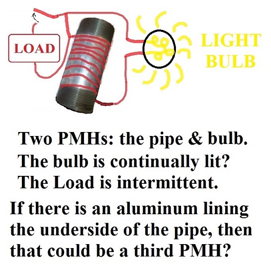
Resonance of a standing wave increases its potential energy?
I forgot to mention what is probably the most important set of possible implied connections that were inspired from reading the quote from the last paragraph of Joseph Cater's book, "The Awesome Life Force" on page 31 and continuing on to page 32, that...
Mr. Cater mentioned that this is the reason for the speed of light phenomenon that whenever a particle approaches the speed of light, it has maxed out its electromagnetic kinetic energy at the expense of its electrostatic potential. A standing, resonant, electromagnetic wave may have a characteristic of non-motion such that its electromagnetic component shrinks yielding an increase in an electrostatic field? In other words, resonance increases the potential energy of an electrical system making a Tesla coil an amplifier of sorts of whatever is possible to generate with any fixed amount of energy? I also thought that whenever the current and voltage coils of a watt-hour meter spin its aluminum disk using electromagnetic forces, that an electrostatic force is being depleted by the braking magnet as it soaks up this electrostatic charge by converting it into an electromagnetic one. There must be an abundant supply of potential energy in the form of electrostatic charge for the disk to have an infinite potential to accelerate without a magnet to brake it? And there must then be an abundant supply of electrostatic energy to convert to a more usable form of electromagnetic energy by the absorptive abilities of the braking magnet. And if the braking magnet is enlarged, then it could act like an electromagnetic capacitor? But because of the braking magnet's permanent magnetization and its small size, then it can only soak up so much before reaching saturation and discarding the excess. This then forces the disk to discard its excess when it reaches its own saturation, and there's no significant benefit obtained. But if the braking magnet were to be demagnetized and enlarged to any amount, and a pickup coil wrapped around it supplying a load, then maybe this would replicate the original intention of but one aspect of Tesla's Tri-Metal Generator. It doesn't vindicate all aspects, since it almost doesn't matter how the disk is spun. I just think the focus of power transfer, conversion, and magnification might be between these two elements and their mutual interaction. This idea is premised on the supposition that the watt-hour meter may be translating electromagnetic energy into electrostatic energy initially to drive the disk, but then does the reverse when the braking magnet slows down the RPM of the disk: it translates electrostatic energy into electromagnetic. And then I thought that if a Tesla coil could be the foundation for setting up a standing wave, or resonance, between all the elements -- the electromagnetic forces driving the disk and the electrostatic forces transferring from disk to braking magnet, then maybe an AC driven watt-hour meter is not the only way to attempt to replicate Tesla's Special Generator since AC may not be easy to resonate into a standing wave? But maybe a pulsed DC from a Tesla coil would be a better way to drive the spin of the aluminum disk of the watt-hour meter if compressed air is not resorted to? In which case, it becomes questionable whether the disk need spin? Because the disk starts to look like the output terminal of a Tesla coil: a hollow, possibly stationary, aluminum toroid? And then I thought that the only thing missing from this scenario is a magnetizable pickup material to surround a Tesla coil's output terminal to convert its electrostatic discharges into a process of electromagnetic absorption into its magnetizable material amounting to an equivalent action between disk and braking magnet of a watt-meter. And if the magnetizable pickup were to be enlarged and wound with a coil, then maybe the output current of this coil could supply a load to whatever degree is needed based on: the power of the Tesla coil and the size of this magnetizable sink.  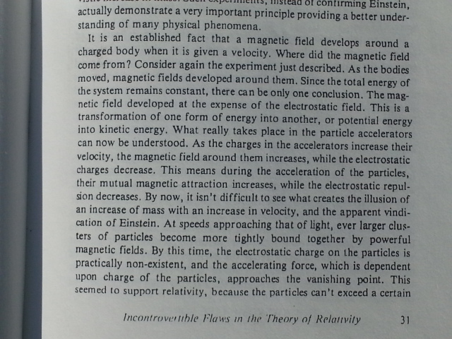 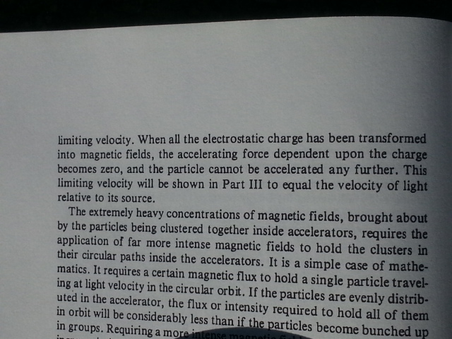
__________________
|
| Sponsored Links | ||
|
|
#22
12-31-2014, 05:22 AM
|
|||
|
|||
|
clearing up some discrepancies...
Referring to the five stages elaborated in post #18...
WIRELESS TRANSMISSION OF POWER NOT INTENDED TO GO VERY FAR I was mistaken. Not all five parts to this system will be in resonance. In fact, it can't be. At least not exactly. At best, maybe in harmonic resonance. Because the iron of the fourth stage will tend to slow down the frequency which it receives generated by the first two stages, #1 and #2, transferred to it by stage #3. This means that stage #3, the output terminal of a Tesla coil, has to be split up into two non-identical harmonically resonant shapes: one remains on top of stages #1 and #2 - the Tesla coil transmitter - while the other is strung out on a wire long enough to take it out of the magnetic field of stages #1 and #2 so that the magnetic field of stages #4 and #5 do not interact with #1 and #2. Stage #3 has to be adjacent, or cuddled up, along side both stage #2 and stage #4 to receive from stage #2 and be able to transfer its static field to stage #4. So, a longish wire could be employed to separate the transmitter from its receiver? 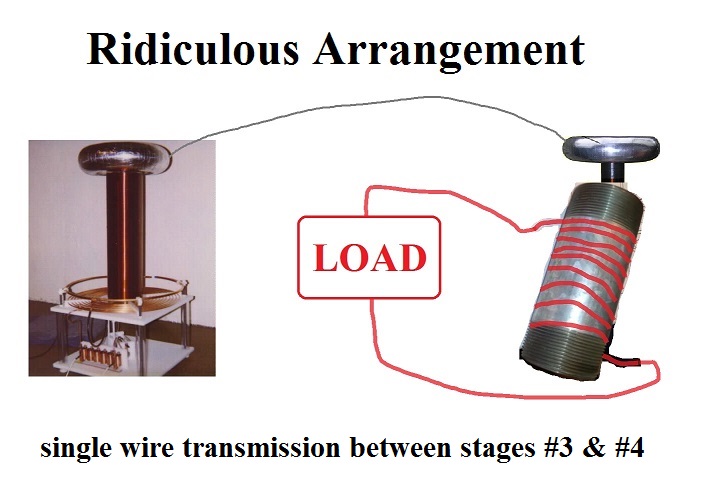 As you can see, this configuration creates problems involving non-resonance and inefficiency, so... Why not shield the perimeter of a Tesla coil with a (magnetizable, non-permanent magnet) {iron?} magnetic shielding? This shield would be a stage #4 wireless pickup reception from stage #3. Surround the shield with a copper coil, stage #5, fed to a load; and possibly line the inner surface of this stage #4 shielding with an electrostatic pickup identical to the stage #3 (aluminum?) material sitting on top of the Tesla coil transmitter. 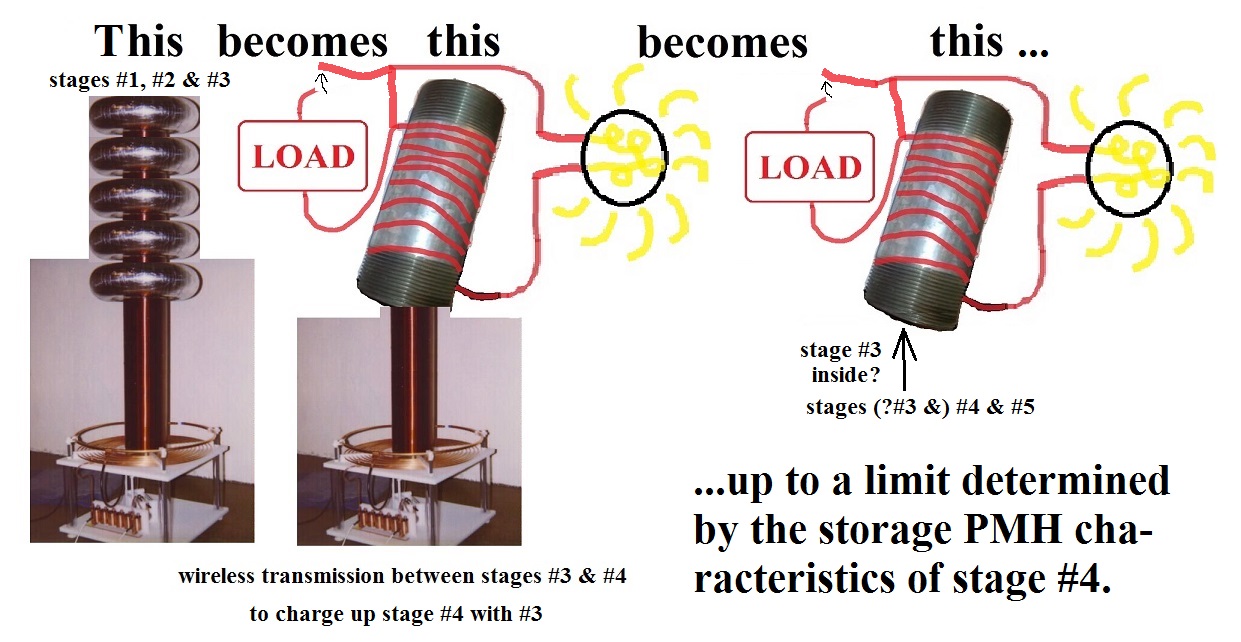 Conceptualizations of the design described above...
__________________
Last edited by Vinyasi; 01-01-2015 at 04:27 PM. Reason: correction for stage #3 and its gap with stage #4
|
|
#23
01-01-2015, 07:43 PM
|
|||
|
|||
|
Structure of Stages #4 & #5
I've been doing all of my initial proof of concept experimentation using my body as my instrumentation of choice to better discern the essential nature of this topic by sleeping on it. Or more precisely, sleeping on an Earthing device - a bed pad - on top of a silk sheet, which is on top of a disconnected Earthing bedsheet which has become so thoroughly oxidized from frequent washings that the silver threads criss-crossing the sheet no longer accept a direct (hard-coupled) connection between my body and the silver threads. Earthing devices, such as: bedsheets and bed pads, are connected to Earth ground via the grounding port of a wall outlet which is correctly wired to standard building code, or else to a grounding rod which is independent of the house wiring.
My focus was the iron core of a coiled winding. My core preference was a toroidal shape. My choice of toroidal shape was based on my need to easily cross wind around the cylindrical mass. I didn't think I could do this on a more massively sized pipe despite the pipe's added iron mass possibly lending that extra umph to these experiments. Each toroidal iron mass chosen was a floor flange weighing about 15 ounces. That's 1/213 of a horsepower, about one half of one percent of a horse (a healthy one, I hope! ") ), added to the output of this device if running at the peak of efficiency (of a TSG) which Tesla has been known to excel. I don't expect that much from myself. Or more seriously, 1/213 of one electrical horsepower (EH) translates into three and a half watts: 746 watts/EH ÷ 213th part of 200lbs. (15oz) = 3.5 watts for experiment #2; 7 watts for experiment #3. ), added to the output of this device if running at the peak of efficiency (of a TSG) which Tesla has been known to excel. I don't expect that much from myself. Or more seriously, 1/213 of one electrical horsepower (EH) translates into three and a half watts: 746 watts/EH ÷ 213th part of 200lbs. (15oz) = 3.5 watts for experiment #2; 7 watts for experiment #3.I used these galvanized floor flanges from the plumbing department of a hardware store, with a 1 & 1/2" ID, to save money instead of using a laminated toroidal core from eBay (although I would have preferred to not use a galvanized piece, but I didn't know then what I know now: they also come as "black malleable iron floor flanges", as well as in larger sizes up to 4 inches inside diameter). But for my very first test, I did not use floor flanges, but used iron nails and green enameled floral wire, #24 gauge, single layer, wound onto the two legs of eight bare iron nails doubled as two nails per side of a square shape. It would have been a true AC transformer in the sense that one leg of the transformer was one coil leading to Earth ground and the other coiled leg went to my Earthing bed pad had not one lead of each coil not been left free to go no where! Later on, I reunited the two coils for improved performance - in a strongly coupled sense, but was also worse because it was only one coil wound in only one direction. Since I was using the grounding port of the electrical wall outlet (not a grounding rod separate from the house wiring), the AC hum bled into this grounded line and the transformer boosted that hum depositing it into my body as a soft vibration which eventually became annoying. So, I substituted with a separate ground leading to a grounding rod outside my bedroom window independent of the house wiring's ground to the AC's neutral. It should be noted that up until the very end of these series of experiments, I did not know that my Earthing bedsheet was not conductive anymore except on the edges of the mattress if I firmly gripped the edge with my hand. Yet, I was still getting some influence or else I wouldn't have noticed the AC hum which also, and not so incidentally, created a condition not unlike that of an overly-caffeinated condition in which I could not fall asleep. In fact, I'd shoot out of bed after a mere five seconds or less of attempting to fall asleep with a tremendous surge of energy and creativity, but along with a mild headache. Once I substituted a brand new Earthing bed pad in place of my connection to a faulty Earthing bedsheet, the benefits which I was experiencing using my Earth-boosting device attached inline with my Earthing bed pad to boost my nightly sleep was nothing short of WOW. Geez! What I'll do for science... My second test used galvanized floor flanges wound with green enameled floral wire, #24 gauge, single layer with a zig-zag winding of one half of the floor flange wound clockwise (CW) and the other half wound counter-clockwise (CCW), 69 turns each half. The adjacent ends of each coil were connected together creating another PMH: a copper wire PMH. At these two points of connection on either side of this toroidal winding, I connected one lead from Earth ground and the other to the Earthing bed pad. This was nice, but I feared that the zig-zag winding on the same iron core might be neutralizing itself in more ways then the mere attempt to cancel out any AC hum from my environment, let alone "balance" the signals interacting between my body and the Earth (not unlike the use of a balanced audio signal to cancel AC hum from electric guitars, and amplifiers experiencing the same bleed-over of AC signal from adjacent live house wiring). So for my third experiment, I split the zig and the zag onto two separate, but identically wound, floor flanges different only in direction of winding: one was CW and the other was CCW. Again, I connected them in a circular manner making the wiring into another PMH of sorts. But this time, I used #16 gauge, insulated, copper wire. Each toroidal winding used 39 turns of a single layer, although it could have accommodated 42 turns. So, I tried to keep my number of turns and length of wire matched for the winding of each of this pair as well as matching the length of all four leads coming off of each winding. Each winding was covered with aluminum foil: one had the foil going into the center hole and covering the hole's inside surface, while the other winding I didn't bother to go inside the hole but merely enclosed the entirety of the winding as one piece. Using terminal connectors, I connected one side of one toroidal winding with one side of the other toroidal winding. But I didn't push these terminal connectors into each other all the way. I left a little space for clipping on alligator clips: one going to the Earth grounding rod outside my bedroom window, and the other leading to the Earthing bed pad. I arranged these two toroids on the floor separated from each other by several inches. A few nights later (last night), I decided to stack one winding on top of the other which had been my initial intention. Then, I had a dream this morning, immediately before waking up... Although I wasn't immediately sure whether or not stacking the toroidal windings was any better than separating them. Yet, the dream may be demonstrating that it was an improvement after all? I was told in the dream that because of what I had done, dogs had obtained the legal right to vote and smoke pot. This was supposed to be something good! I've got all kinds of guesses what that could mean, but still don't know and am not worrying about it.
Continuing with the discussion... I'm pondering whether or not the iron pickup of stage #4 should be two separate windings, not merely one, matched CW vs CCW, and stacked in pairs (could be multiple sets of pairs)? In other words, has my Earthing experiments been merely an examination of stages #4 & #5 (and possibly a little examination of stage #3 as well)? And leaving me little choice but to speculate on how to charge up stage #4 so that stage #5 could run a load? {I'm referring to the use of a Tesla coil in the previous post #22} 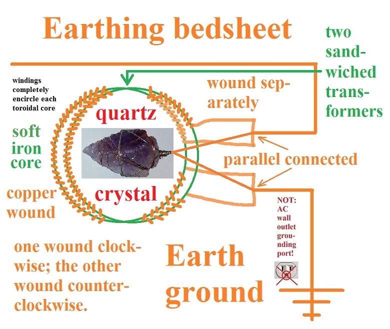 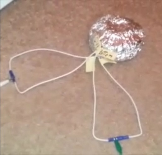 Sandwiched together, one coil laying on top of the other, is the best configuration. Although two of each, wound clockwise and counter-clockwise, are a minimum configuration, multiple sets of two could be stacked up and charged with a Tesla coil secondary inserted through the center of the stack, and then removed. 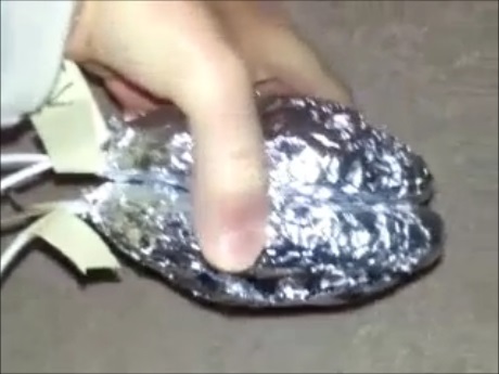 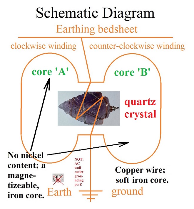 Spread out apart may look nice and neat, but is not as good as sandwiching the two coils together - one on top of the other. 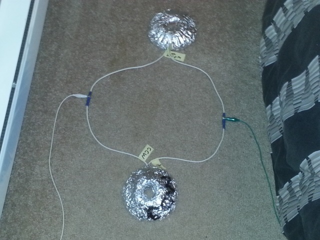
__________________
Last edited by Vinyasi; 01-05-2015 at 01:49 AM. Reason: added some photographs; made a minor correction
|
|
#24
01-02-2015, 10:38 PM
|
|||
|
|||
|
Redesigning Stages #3, #4 and #5
Quote:
Take the cylindrical shape of stage #4 and place it inside of stage #3 as an iron PMH and wrap/wind stage #5 copper pickup coil around stage #4. In other words... 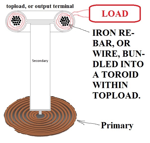 Using these YouTube instructions as a model from which to begin... world's easiest fastest toroid for tesla coil Following the directions of the above video from YouTube, if we took an aluminum ducting from the hardware store (probably used for dryer venting) and inserted into it a bundle of iron rebar (the rebar having first been wound with heavy copper wire), then both could be shaped into a circular shape with the copper coiled rebar suspended in the center of the aluminum ducting. Then the ducting could be sealed around the circular rebar cored copper coil and the ducting outfitted with its two Marie Calendar pie pans and then the aluminum duct plus pie pans could be hooked up to the single wire coming off the top of the secondary of the Tesla coil. And the two copper wires (coming out of the aluminum ducting from their winding around the circularly bound rebar) can go to a permanent small load, such as a small light bulb, and continue onward in parallel to a switch and two terminals for connecting to any number of intermittent loads. To prevent any hazard of internal arcs frying off the insulation from the copper wire on the inside of the aluminum duct / output terminal, maybe iron mesh in the form of steel wool has to be stuffed into the space surrounding the copper wire wound rebar between it and the interior of the aluminum duct?
__________________
Last edited by Vinyasi; 01-05-2015 at 02:53 AM. Reason: added a schematic
|
|
#25
01-02-2015, 11:56 PM
|
|||
|
|||
|
Redesigning Stages #3, #4 and #5, v.2
Quote:
With a spinning topload - or output terminal - of a Tesla coil, the demagnetized braking magnet can definitely be a 'C' shape surrounding the cross-sectional circularity of the toroidally shaped topload. The buildup of charge on the topload should get it to spin just like the spin of an aluminum disk in a watt-hour meter. But I'm still not clear why it spins one way versus the other. All I remember is the definition of the operation of a homopolar generator of Tesla: the disk wants to throw off its buildup of charge by spinning itself. So, its voltage diminishes from its center to its periphery. The explanation in the handbooks on the subject of watt-hour meters say that spin is imparted to the disk as the result of eddy currents. That doesn't help me understand. I'm still spin-clueless.
__________________
Last edited by Vinyasi; 01-03-2015 at 02:12 AM. Reason: clarity and grammar
|
|
#26
01-03-2015, 07:35 PM
|
|||
|
|||
|
Anything is possible with a clear, clean, crisp electrostatic signal.
Tesla's Special AC Electrostatic Generator At its heart, Tesla's Special Generator is an electrostatic AC device. We make the mistake of basing our "modern" generators on Tesla's prior art: an electromagnetic design which creates a fuzzy signal of unsuitable quality for boosting into a more powerful output. So, we have to accept an electromagnetic generator's meager output for whatever it's worth and leave it at that - a very inefficient setup. But with electrostatic generation of power, it's as if we dress a beast with two layers of electromagnetic clothing after first creating this perfect animal out of electrostatic AC signals. The first layer of clothing is a magnetic conversion of the beast's naked body, followed by a second layer of clothing composed of an electric current emanating from the prior layer of magnetic clothing. This final layer of clothing supplies the load/s. The fundamental flaw in our investigation of whatever makes anything so very, very powerfully special is not some secret source of energy, but an extremely clear, clean, crisp audio-like signal - in this case, an AC signal coming from Tesla's Special AC Generator. Once a crisp signal of high fidelity is first created - no matter how weak, it will produce another crisp signal upon its amplification. In this case, amplification is achieved using the analog method of incorporating non-magnetic, but highly magnetizable iron as the pickup material of choice for imparting a magnetic field to a crisp electrostatic AC signal. The signal itself is created by an aluminum something or other alternating its movement/s to create this AC signal. The copper coiled wiring surrounding the iron pickup then carries a current away to supply a load. If we wanted to create a powerful AC generator and all we managed to do was create a fuzzy signal with lots of distortion, then when that signal got boosted, it would be even more fuzzy than before. So much so, that it would be a mess and useless to even consider utilizing much less expect it to be a powerful signal. It doesn't matter how faint the initial signal is when it get's created; it's the clarity of the signal that counts. Power is easy enough to add; anybody can do that. But cleaning up a fuzzy signal once it's been made fuzzy to begin with isn't easy and doesn't get any easier once it's been amplified. So why go to all that wasteful trouble? Why not do it right from the start? I think that Tesla's Special Generator was an outgrowth of Tesla's investigation into developing further his synchronous motor and generator designs. Because I think there are two types of crisp signals which can be generated by his Special Generator and they're both an AC signal generated by a synchronous method. One type of signal is a spike excellent for radio broadcast communications. The other type of signal is a sinusoidal wave form which was probably used for powering the electric motor-driven propulsion and various other loads on board Germany's WWII Electro-U Boats. This is the signal of choice for all of our power generation, but we don't use this method of producing power in today's society - or do we? At least to some extent, we know we do. But whether or not our synchronous generators are special generators - well, only imagination or the whistleblowing of an insider could ever clear up this mystery. The spiked signal is probably created using William Lyne's supposition in the back of his, "Pentagon Aliens", book: a reciprocating piston moving no more than a sixteenth of an inch. But I bet that piston rotated as well as reciprocated. And I'll bet it alternated its direction of rotation for every half of its production of an AC cycle. It probably had squirrel cage style grooves cut into its sides to act as baffles and there may have even been matching grooves on the interior surface of the tube in which the piston reciprocated. These spiraling grooves would make the piston rotate as it moved in either one direction or its opposite up and down the length of its 1/16th inch movements. Any movement of a piece of metal, if performed fast enough, will generate an appreciable electrostatic charge upon that metal. This is known as the Searle effect and is briefly described in Joseph Cater's book, "The Awesome Life Force". So, distance of reciprocation is not the issue here just as William Lyne suggests; but speed does matter. So in all likelihood, the frequency chosen to operate Tesla's Special Generator is probably a very high one. In any event, the signal generated by an electrostatically reciprocating charge will be a very clean, crisp signal of an AC characteristic. And because of the sudden and drastic reversals occurring using this Special Generator's cylindrically shaped piston, the signal will be suitably a spike - and not a sinusoidal wave - good for radio communication (possibly employing Tesla's Wireless technology). This is where I digress from presumed notions of how to generate an AC reversal of electrical sign with a huge sharp increase, or decrease, in between each half phase of an AC cycle. Since this is an analog method employing no digital methods we have come to depend on, a novel method had to be used to effectively and simply do a hundred years ago what we'd probably use solid state integrated circuits to perform today. But this merely takes care of the need for communication between land and sea. I believe that power generation was created on board these Electro-U Boats using a toroidal shaped non-reciprocating rotor in a toroidal shaped shaft to generate a sinusoidal AC electrostatic signal. And these toroidal pistons were probably positioned surrounding each cylindrical piston with each piston at right angles to each toroidal piston paired with it. In other words, the axis of rotation for each toroidal rotor was congruent with the axis of reciprocation for each cylindrical piston. The centering of each cylindrical piston along the axis of rotation for each toroidal rotor would greatly enhance the sharp spikes generated by each cylindrical piston. It would also cause the cylindrical piston to act as a master and each toroidal rotor paired with each cylindrical piston to act as its slave. So, the cylindrical piston set a very sharp beat (just like a metronome), while the toroidal rotor further magnified this electrostatic field occurring all along its axial center wherein is conveniently positioned each cylindrical piston to take advantage of this electrostatic amplification. The whole process, as you can imagine, is mutual synergistic encouragement. I also presume there are eight total piston/rotors in all...
The rough first draft of this post, in the form of an audio recording, is located here. Quote:
__________________
Last edited by Vinyasi; 01-05-2015 at 07:01 AM. Reason: additional opening paragraphs...
|
|
#27
01-06-2015, 01:35 AM
|
|||
|
|||
|
Could a Crystal Oscillator Replace the Reciprocating Piston?
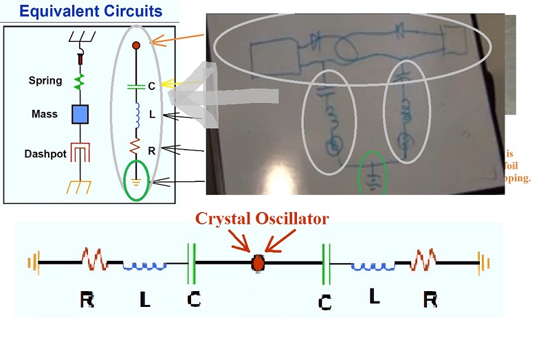
Could a crystal oscillator replace the pneumatically driven, reciprocating piston of Tesla's original design (circa, 1895) and still produce a clean, crisp electrostatic signal for magnification and transformation into an electromagnetic output supplying a load?
To illustrate, I'll make an analogy between Tesla's Special Generator and an Earthing amplification device which uses an iron cored, toroidal, copper wound coil with a piezoelectric crystal at the center of the toroidal coil and the entirety wrapped with aluminum foil in the photo below... Following the lead of posts #24 and #26 and using an excerpt from the following text's page 3-19 (PDF, pg. 69) ... A TUTORIAL ON QUARTZ CRYSTAL RESONATORS AND OSCILLATORS, BY JOHN R. VIG  Notice how the right-hand "Equivalent Circuit" looks like the receiver on a Tesla coil minus the primary (plus driving circuit) in which the red dot is the addition of a piezoelectric oscillator representing the streamers coming off of a Tesla coil's topload, 'C' is the aluminum topload, 'L' is the secondary, and 'R' is the air core of the secondary plus the distance between the topload and the primary? 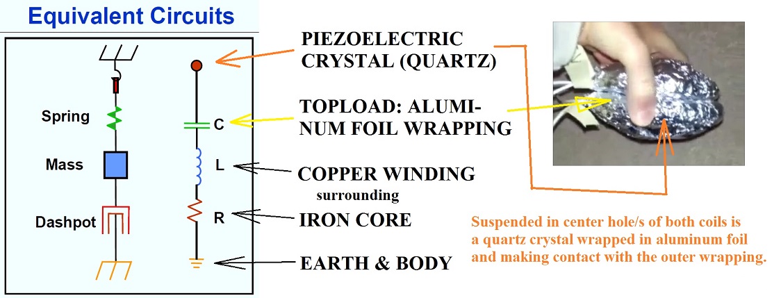 I had previously supposed that glass was the unsung hero in this circuit. And not knowing what to do with it or with the aluminum ingredient of Tesla's Special Generator, I inserted a capacitor into this circuit made of both ... ... but then opted to exclude it as being superfluous (right intentions; poor execution). But I hadn't considered the use of a vibrating crystal as a substitute for Tesla's reciprocating piston. So, I guess my hunch of glass was a lukewarm hunch after all since glass is somewhat of an amorphous melt of quartz. Plus, I had no idea I was inadvertently using the symbol for a crystal oscillator for what I thought was a more detailed drawing of a glass plate capacitor... !  Audio / Video blogs ... PiezoElectric Oscillators. Placing an Amethyst Arrowhead in the Center of a Transformer's Aluminum Foil Wrapping as an Earthing Appliance's Very Vague Example of a Piezoelectrically Driven Special Generator of Nikola Tesla.
__________________
Last edited by Vinyasi; 01-08-2015 at 07:03 PM. Reason: additional audio/visuals plus remove some text at the end...
|
|
#28
01-06-2015, 04:37 AM
|
|||
|
|||
|
Remarkably similar...
__________________
|
|
#29
01-06-2015, 06:00 AM
|
|||
|
|||
|
Maybe the Germans were using outdated Tesla technology during WWII?
Maybe the only reason the Germans had to rely on a reciprocating piston to power their implementation of Tesla's Special Generator - rather than anything better - was on account of their having stolen, in 1899, Tesla's patent on the liquefaction of air (patented by a Mr. Linde in Germany immediately after Tesla's lab caught fire)? Thus by theft, they had ostracized themselves from any further contact with Tesla on the development of his Special Generator. Tesla may not have been using this older version of a reciprocating piston anymore by the time the Germans implemented it during WWII? But the Germans made up for their lack of contact with Tesla by thieving yet again from the man who had worked with Tesla to develop this generator, a Mr. Dort (according to Mr. Lyne in his "Pentagon Aliens" book).
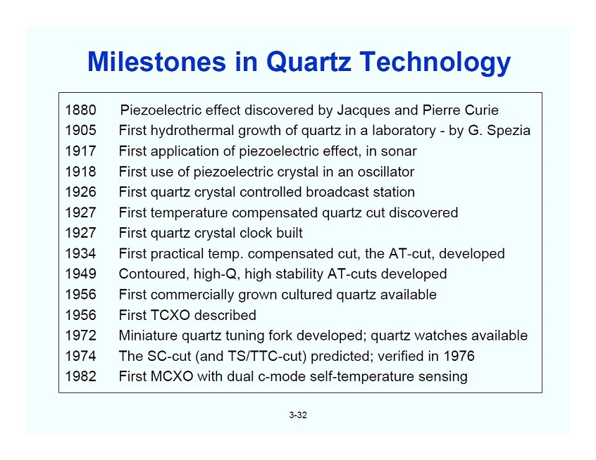
I'm hard put to think that Tesla would have been restricted to pneumatically driven reciprocating pistons by the start of WWII as the only way to drive his Special Generator. How could an innovator in his field ignore the development of piezo-oscillators as indicated by this excerpted page 3-32 (PDF pg. 82) from out of ...
__________________
|
|
#30
01-07-2015, 08:08 PM
|
|||
|
|||
|
Version two: a homopolar tri-metal generator...
Ok, so reciprocating pistons might be one version. But what about the story of my electrician's coworker? His version of a tri-metal generator was the size and dimension of a spiral bound notebook.
One thing about the study of the watt-hour meter that I have not described is the vague similarity between the jeweled bearing (of white sapphire or diamond) on the bottom of the bronze vertical axle (to which the spinning aluminum disk of the watt-hour meter is attached) and a piezoelectric oscillator. The jeweled bearing may be thought of as a crystal oscillator in as much as the bearing will vibrate as the disk of the watt-hour meter spins. Or, it may not vibrate until "center of load" is reached (in which the load equals supply, as described by Mr. Dort via William Lyne). So, I'll assume that the jeweled bearing is serving as a memory component, not unlike an EPROM retaining a state of memory whenever a computer is switched off. So, let's see...
__________________
|
|
|
|
|
Please consider supporting Energetic Forum with a voluntary monthly subscription. For
One-Time Donations, use admin@ this domain > energeticforum.com |


 Does a spinning toroidal output terminal require perforations all along its sides (similar to the spinning aluminum disk of a watt-hour meter)
 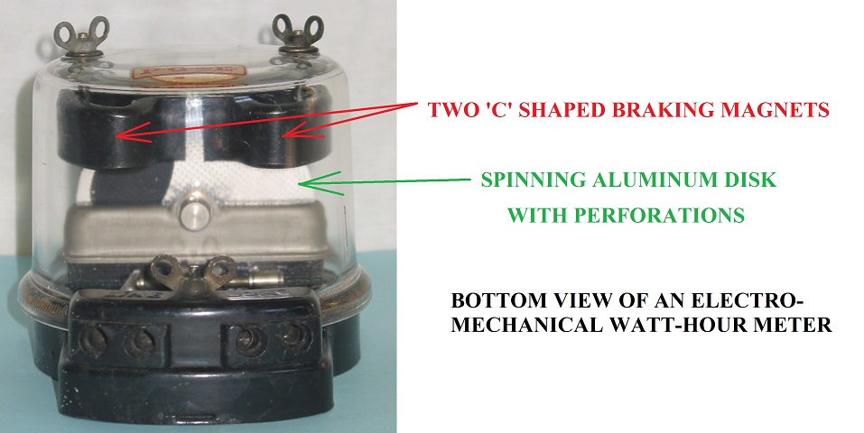 to enhance its ability to spin? Or, should it remain stationary?