When its brush contacts are wired in such a way that they sit between the commutator and the rotor. This wiring is advantageous as an alternator. If they are positioned on the side of the commutator opposite the rotor coils, then they will not amplify their output. This latter wiring is advantageous as a motor.
None of the simulations described on this page are overunity unless parametric excitation is engaged.
Standard approach to the recharging of batteries requires a slight voltage higher than what the battery measures and in reverse polarity to it. So, if a battery is reading +6 (positive six) volts, then I need to provide -7 (negative seven) volts in order to overcome the battery's 6V. Otherwise, current won't flow into that battery. And if current won't flow, then the battery won't recharge.
But what if I don't want to take the direct approach (which can be dynamically metered as it is taking place in real time with a fancy display on the EV's console)? What if, instead, I take the indirect approach: one which cannot be metered, but requires rules of thumb to help me negotiate through it? Such is the case with what I am proposing based on John Bedini's work and that of one of his many followers and admirers: Dave Bowling.
What I am proposing is nothing short of heresy to our common sense. It is this...
Suppose we don't try to force current into a battery by fighting its voltage with a greater voltage of our own (and in reverse polarity to the battery's voltage orientation)? Ergo, what if we lay down our weapons and give up war? What if we simply want to spike low voltage, moderate amperage uni-directional current at the battery and then test it afterwards using standard procedure of a known load across its terminals, say: a one Ohm resistor, and then measure in parallel across that small load to see if its voltage has changed any? By trial and error, a vague general understanding may arise of what it takes to regenerate a dead battery without attempting to recharge it, yet end up with a battery more likely to want to allow itself to be recharged since we were so gentle with it. It's worth a try...
Dave Bowling's setup – at its core essential nature – is a modified improvement of John Bedini's three battery rotation scheme and similar to a Joseph Newman device.
The clue to the latter analogy is given by Dave and other bloggers on the EnergeticForum thread (devoted to this topic) in which they suggest that if the motor doesn't turn by itself in five minutes, then try hand turning it a bit to get it to start. That's exactly how Newman started up his motor: by hand turning it – very vigorously (since he was a body builder and his motor required it).
This tells me what I need to know to simulate Dave's setup. It tells me that (at least) one secret lies in the little appreciated fact that a spinning rotor produces an A/C rotating magnetic field in a D/C motor while the rotor inside an A/C motor is spun by a rotating magnetic field surrounding it.
Normally, we provide a positive resistance whenever we use a pileup of voltage as our source of current. This is a positively resistive model since the voltage pushes the current from behind creating eddy currents in the form of back EMF. We also have to pay a considerable energy cost to continually provide for this voltage source since we are simulataneously draining from it. But there is an alternative...
What if, instead of pushing from behind, we pull from ahead? This will happen if we use negative resistance. And we can achieve negative resistance through multiple agencies.
Newman used a massive coil...
Although Newman's massive coil provids positive resistance against current flowing from its battery pack, it is also a negative resistor for the magnetic field rotating in the center of that massive coil (emanating from its spinning permanent magnets). All I had to do to recognize this fact was provide a miniscule voltage source on the order of micro volts to my simulation of the rotating field of magnetism surrounding the spinning bar magnets (in the Newman motor) to witness a gargantuan quantity of current arising from where? From that tiny voltage source prompted by the massive coil's pressure of resistance acting against the battery pack.
It's a question of perspective...
What constitutes positive resistance for the battery pack (in the Newman device) is negative resistance for its rotating magnetic field surrounding its spinning permenent bar magnets.
The massive coil of Newman's device actually draws current from out of the rotating magnetic field of the spinning permanent magnets at the center of his machine. And that massive outpouring of current is for free (since we don't have to pay for it other than provide for his setup) and will top off his machine's battery pack with sufficient recharge to keep them fully charged at all times (since they're not expending much current, as it is, anyway!).
In Dave Bowling's setup, sparking brush contacts on the commutator don't deplete the energy provided to recharge the battery pack as in the Joseph Newman device. Instead, they replace Newman's massive coil as a negative resistant, suction for A/C current to recharge Dave Bowling's batteries if it is wired with its brush contacts on the side of its commutator facing towards its rotor coils.
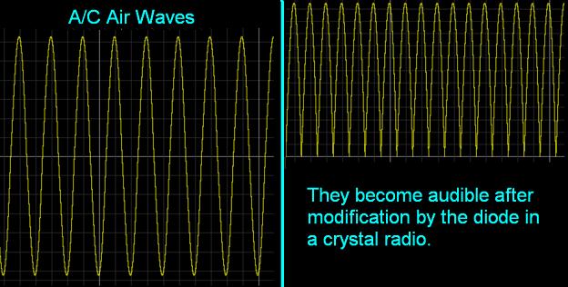
But if wired such that its brush contacts are on the side (of its commutator) opposite its rotor coils facing towards its surrounding circuit to which it is attached, then this makes a great motor since its waveforms are modified A/C sinewaves and sinewaves are helical, namely: they are screw-shaped to help rotate the motor's axle.
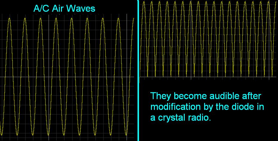
The diode in a simple, crystal radio modifies radio waves in a similar manner to make them audible.
A/C Air Waves vs Audible Radio Waves
To describe how I model the rotating magnetic field of a D/C rotary device: using a transformer and an A/C voltage source, I'd like to make a comparison between an A/C rotor and its D/C equivalent.
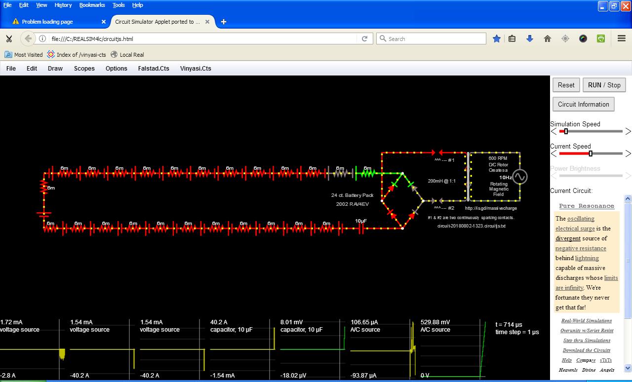
The primary of a transformer (on the left-hand side of this simulated model) is the rotor inside both motors while the magnetic fields of either rotor is represented by the secondary of the simulator's transformer (on the right-hand side of this simulated model). In the case of an A/C rotor, the squirrel cage rotor (inside the A/C motor) spins around immersed in the A/C armature's magnetic field. In contrast, the D/C rotor spins around inside the magnetic field which it creates. Both A/C and D/C magnetic fields drag their respective rotors along. A D/C motor's commutator translates its rotating magnetic field into a D/C flow-pattern prior to allowing this electrical flow to exit the D/C rotor coils and enter the circuit to which the motor is attached. This is modeled, here in these simulations, by a full bridge rectifier consisting of four diodes in a square formation on the far left of the image, below.
A few pointers ...
- Stout AWG #6 battery cables are used to connect between adjacent batteries to reduce cable resistance to one Ohm or less.
- Although I suggest polarity of the D/C motor (in my simulated model) to have the positive terminal of the D/C motor connected to the positive terminal of the pair of good batteries and the negative terminal of the D/C motor connected to the positive terminal of the dead battery, you may discover greater advantage if you turn the motor's connections around? Each case is a unique blend of multiple factors which has not been fully analyzed by competent engineers. This procedure remains experimental although it has ten years of a dozen, or so, individuals' experiences who have successfully replicated Dave Bowling's original work.
Let's review this special case diagram
of a Three Battery Charger, again...
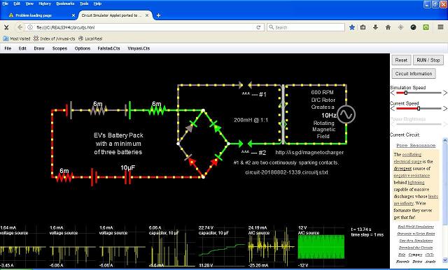
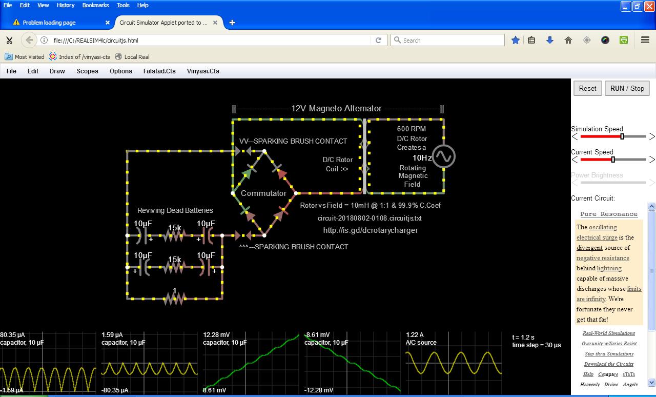
The commutator's sparking brush contacts separate the A/C power source on the right-hand side (arising from the spinning magnetic field of the magneto's rotor coils) from the batteries on the left. Their relation is governed by the inductance of the rotor's coils simulated, here, by the transformer coils plus the coupling coefficient between the transformer's primary and secondary coils on the left and right, respectively, which represents how efficient does the rotating magnetic field (on the right) transfer its power to the rotor's coils (on the left)? A ghost of an A/C shaped waveform remains on the left after the sparking brush contacts finish chopping them up into spikes due to pressure buildup across their gaps suddenly releasing their pent up pressure in the form of spikes.
If your intention is to amplify (with brush contacts on the side of the commutator facing towards the rotor coils), it matters how many good batteries are strung in series. Any quantity of batteries greater than, or equal to two, will result in higher or lower amperage spikes across all of them, respectively. Less than two good batteries shuts this circuit down. Kaput! Nada... No results unless a minimum of two good batteries are in series. The capacitor (acting analogous to a dead battery) is optional.
You know you must be in negative resistance heaven when the current draw (at the source) goes down while the secondary source current (at the sparking brush contacts) continues to match the load's increase in demand for more current (by the addition of more batteries)! The secret lies in the spark gaps literally giving up unlimited current on demand from out of (seemingly) nowhere. Enlarged current only begins to appear after battery #1 at battery #2 and continuing onward past battery #3 and #4, etc. This is why two batteries are the minimum requirement to see maximum gain. The capacitor (in this situation) is optional. Yet, it is useful since it accelerates the amplification of spiking current. Most of these spikes point in the negative direction indicating a hint at recharging our battery had the voltage level of these spikes been at war with the battery's voltage!
Let's see if I can explain this a little bit better...
The batteries give up some of their current in the direction of the sparking brushes at first prior to the brushes beginning to spark. This charges up (energizes) the brushes with current followed by the energizing of the rotor's coils. Once the sparks commence, this temporary storage of current is used, and reused again and again, to charge the batteries despite their voltage remaining positive against such flow. My assessment is this: the negative resistance of the sparking brushes overcomes the positive resistance of the batteries' voltage to successfully charge these batteries with reverse current flowing out of the negative terminals of the batteries. The rotor is (now) acting as a generator (empowered by its tempory storage of energy) rather than as a motor using energy "borrowed" from the batteries, but then sent back to the batteries, to charge them. It's an interesting way of doing things since no new energy is needed from outside this circuit to perform the charging of this battery pack other than one requirement: the magnetic saturation of the iron core of the rotor by an outside source, such as: a permanent magnet (for instance). Beautiful, isn't it? We don't pay for energy – but once – when we first acquire the energy of the batteries. Instead, we reuse it. So, we're not recharging the batteries so much as we're preventing their discharge since energy is being continually recycled in reverse direction (from their normal direction whenever they discharge themselves).
Meanwhile, this recycled energy is also energizing the capacitor (which could just as easily be a dead battery). And if this capacitor is displaced by one or more coils, then these coils become oscillating A/C sinewave motor coils suitable for a very slowly moving electric car, or some other device (like an air pump of low resistance) which slowly, but surely, will boost its power if resistance on these coils is not too great.
It's possible to add an electric motor to these circuits. The frequency to which the capacitor wants to oscillate is a little slow for an A/C motor and is locked into a constant frequency which won't do if you're trying to drive a car at varying speeds. So, some adjustment is necessary to take this proof of concept to the level of practicality for a self-charging electric car. That's beyond my expertise. I'm just an idea guy.
The batteries are subjected to very high frequency (square waves?) of current despite their flatlined D/C voltage. These spikes increase in absolute value (with negative polarity) per additional voltage arising from more batteries placed in series. In this example, I've grouped the batteries into two groups of 72 volts, each.
The voltage source on the right hand side of the transformer can be any type (square wave, pulse, A/C, D/C, etc) in any amount of voltage. It's not the source for powering this circuit. It's purpose is to merely magnetically saturate the magnetizable core of the transformer (without which, this circuit can't function). So in a sense, you could say it's a source, but not a current source.
The sparking commutator brushes are responsible for orchestrating the current gain. But the source of this current is among the batteries, themselves. They are tricked, by the sparking commutator, into giving up their current in a negative direction – rather than in the normal positive direction. And these sparks do this without recourse to brute forceful use of a voltage greater than the batteries' voltage of twelve volts (in order to overcome the batteries' tendency to output current on the basis of their twelve volts to back them up).
In other words, normal convention makes it impossible to accept current into a battery in a negative direction (to charge them) unless the battery's own voltage is overcome with an outside voltage greater than its own and in reverse (inverted) polarity. But spikes of current can pass through a battery's voltage barrier with the added advantage of no harmful aging (which normally occurs with standard charging methods). This method may take longer than usual to charge a battery, but the battery ages more slowly and, thus, will last a lot longer. And, some batteries are not totally dead. But by conventional standards, they are. It is these batteries – in the middle of extreme deadness and not so deadness – which this style of charging may be of benefit by possibly reviving them.
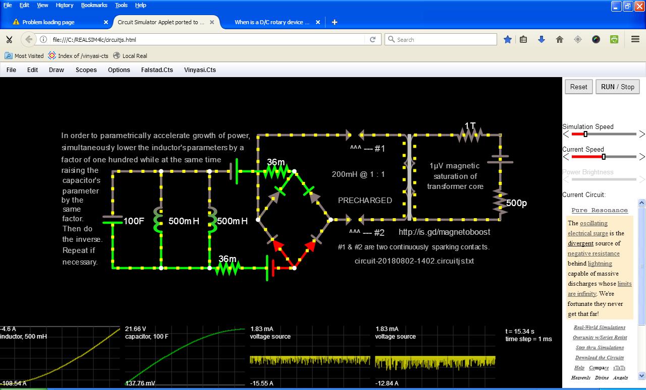
To accelerate time (dilate time), I've chosen to use parametric excitation to boost this circuit's overall power. Time dilation is an acceptable method for bypassing Conservation of Energy. But this circuit simulation will slowly increase in overall power, anyway, so long as the two resistors in series with each of the two inductors are below one milli Ohm. These resistors represent a "light" load upon these motor coils of an EV wound in pairs of counter-winding to cancel any beat frequencies which may occur.
In these simulations, I suggest a time dilation of a factor of: twenty, ten, five or two, for varying capacitance and inductance for energy gain. Anything less, such as a factor of: 10% added or subtracted to the parameters of inductance and capacitance, will dilate time alright, but backwards (rather than forwards) in time resulting in the decomposition of electricity into its constituent ingredients of its electric and magnetic fields. The resulting appearance will be that of electricity seemingly disappearing! It didn't disappear (from space). But it can move around in time reappearing in space at a sooner or later point in time. This still conserves energy, but just not in the normal manner to which we are accustomed!
Paul Falstad overlooked resistance inside of batteries. So, to make these circuits a little bit more realistic and a little less over-reactive, I've added one-half milli Ohm per volt using the NiMH (nickel metal hydride) batteries designed for the RAV4EV from 1998 to 2003 which possess 6 milli Ohms internal resistance when brand new as my arbitrary standard.
For some uncanny reason, this style circuitry (excluding the D/C Rotary Charger) requires a minimum of 36 volts at either the rotating A/C magnetic field on the right-hand side of the transformer (#36V) or else a total of 36V as measured on the batteries to the left or both. But not some volts from one and the balance from the other. No way. It has to be provided, in full, from either or both as if to suggest hints of Dave Bowling's 3 Battery Generator (3 count of twelve volts, each)? There must be something mysteriously magical about this D/C quantity?
Perhaps we can never answer all of our questions? But just keep asking them more and more...?
|