|
Four Micro-Cap simulation files (in a 31.6kb zip file) analyzing the power output for all of the significant components of the ON variation of the following circuit to determine whether the outcome for each component is positively signed in polarization (indicating the consumption and conversion of power obeying the symmetry of the Conservation of Energy), or else is negatively signed in polarization indicating the synthesis (generation) of power obeying the asymmetry of the self-amplification of energy, ie. more energy accumulates than exits a circuit. This is intended to reflect only one aspect of the passive sign convention pertaining to the signage of power and its functional consequences, ie. the growth or decay of power as an organic function. The scope of this question is inspired by Jim Murray's promotion of the idea that: for the analysis of whether or not a circuit is performing as an overunity device, complete thoroughness is required.
Sixteen screenshots, follow, of the schematics and outputs for a circuit's 147 second run-time...
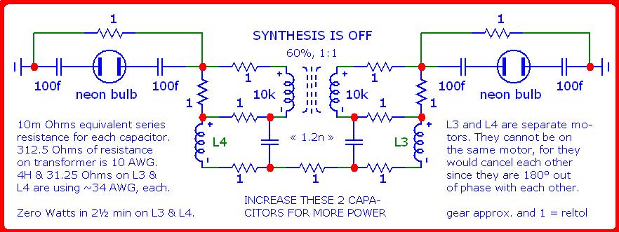
The first three screenshots pertain to a relatively OFF condition by shorting out a pair of capacitor|spark-gap|capacitor sandwiches, involving capacitors: C2, C3, C4 and C5, flanking either side of this circuit to prevent the generation (synthesis) and accumulation of power. The two spark gaps are high voltage tolerant, neon gas canisters.
Hint...The synthesis of electricity is derived from its constituent ingredients of: magnetism, dielectricity (electrostatics) and time, ie. the generation of power (more from less; not something from nothing).
The ambient environment provides all the energy which is needed, not to power our circuitry, but to stimulate it to self-amplify whatever scant quantity of electrical energy already pervades our natural environment and then convert this reactive power into real power using resistance as just one example of a tool to effect a useful outcome.
The synthesis of electricity is OFF due to shorting out each of a pair of capacitor|spark-gap|capacitor sandwiches with a one Ohm resistor...
|
|
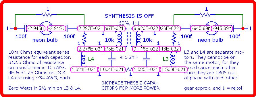
Nodal voltages of the OFF condition...
|
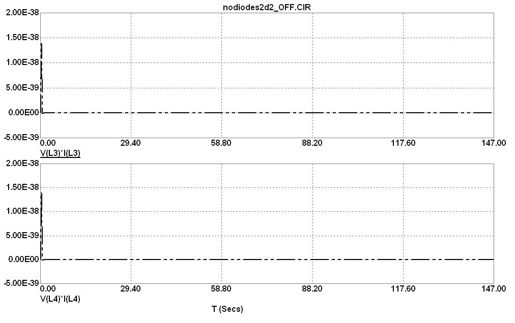
The graphical wattage (without numeric data) of inductors, L3 and L4, indicates an initial surge which quickly dies out towards an asymptotic limit of zero...
|
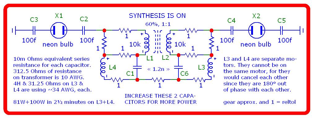
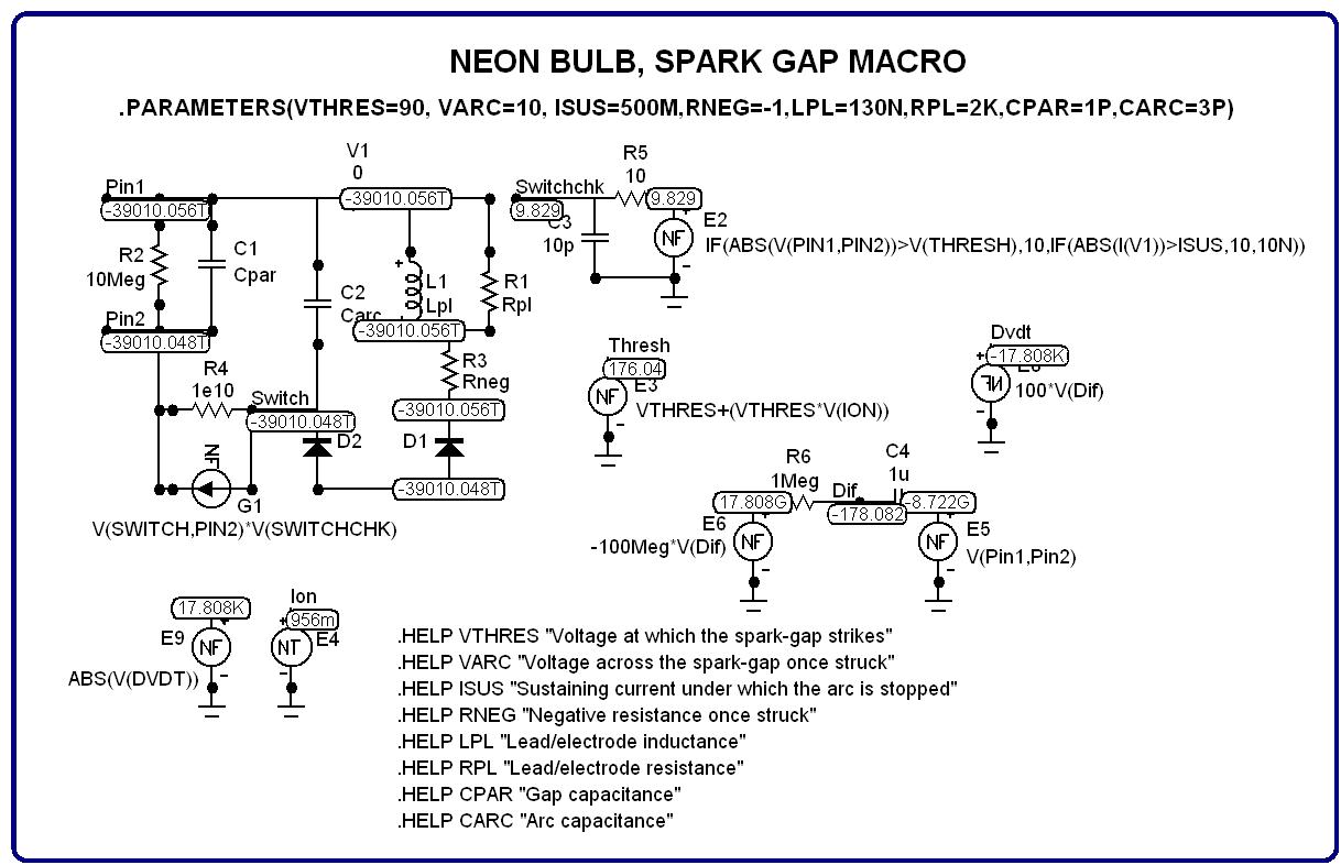
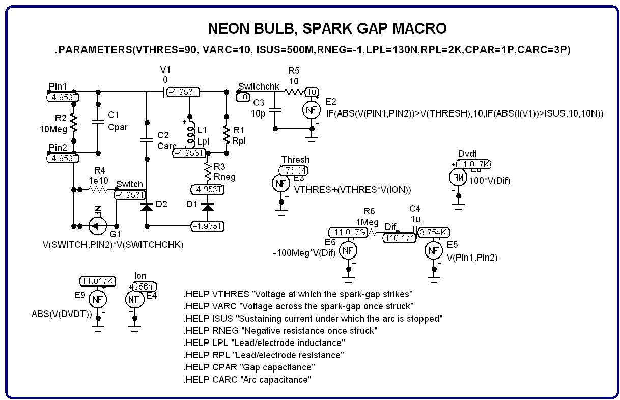
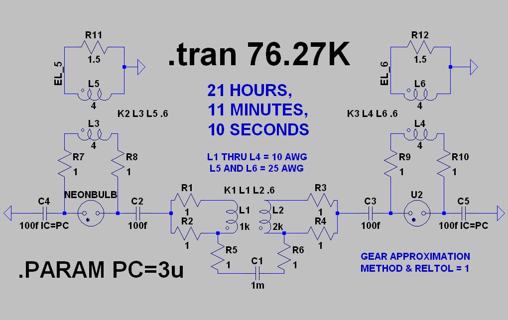
This is the circuit under investigation...
|
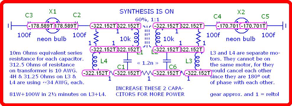
And here are its nodal voltages after 2 & 1/2 minutes of simulated run-time...
|
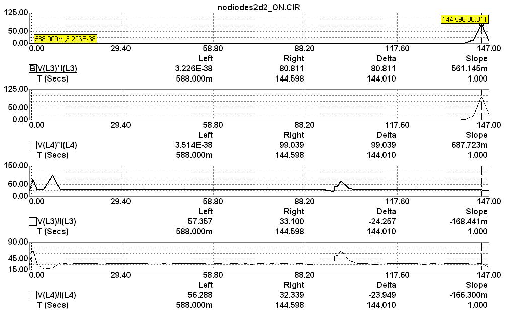
Wattage of motor loads, L3 and L4, with their impedances...
|
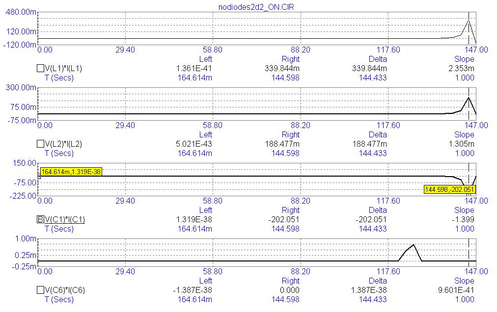
The wattage of the transformer, L1 and L2, in the center of this circuit plus the two nano-Farad capacitors immediately beneath it, C1 and C6...
|
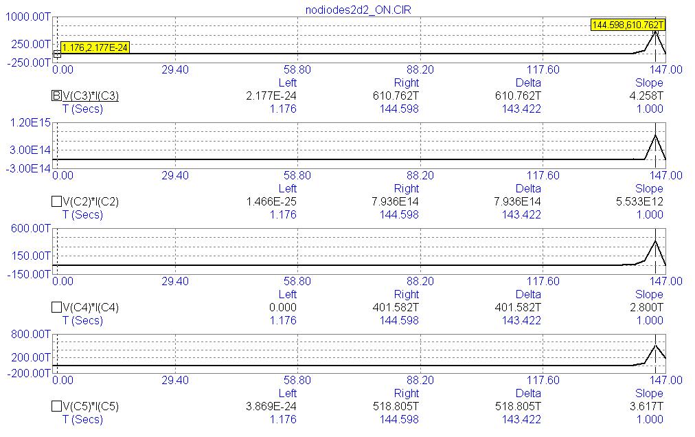
The wattage of the four capacitors, C2, C3, C4 and C5, flanking either side of both spark gaps...
|
The nodal voltages of the spark gap, macro (equivalent circuit) modeling the neon bulb on the left-hand side of this circuit, labeled: X1...
|
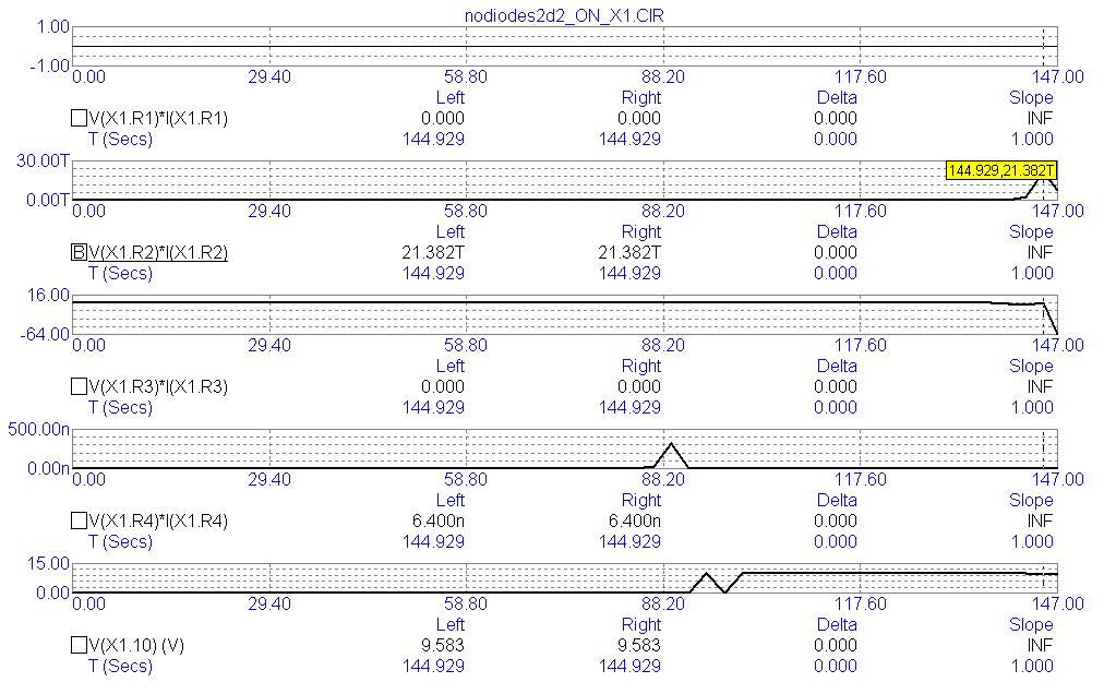
The wattage of the four resistors within the spark gap macro, X1, plus the nodal voltage for node number: X1.10 labeled: "Switchchk". This node displays when is the spark gap ON (arcing) or OFF as determined by the several logical components within this macro.
|
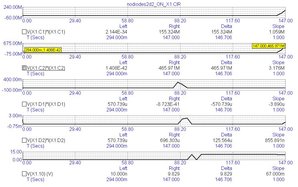
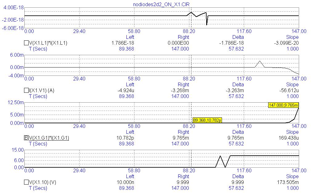
The wattage of capacitors, C1 and C2, plus the wattage of the diodes, D1 and D2, within the spark gap macro, X1, plus a repetition of the nodal voltage for node number: X1.10 labeled: "Switchchk" serving as a reference throughout the duration of this circuit's run-time. I do this, because I have discovered that the presence of a spark gap can have a profound effect regardless whether or not the spark gap is actively firing. Just by its presence, alone, overunity may manifest leading up to its ON condition which merely accentuates its pre-existing overunity of output. Yet, whether a spark gap is ON or OFF alters the behavior of a circuit in as much as different components of the circuit take turns (swap roles) of generating power (in its useless condition of a standing wave of its current in total reversal of the phase of its voltage by one-half cycle of oscillations) versus which components are consuming, and converting energy for its exportation out of the circuit as: heat, or light, etc, whenever its voltage and current phases are in sync without any phase separation between them (exhibiting maximum efficiency of power factor).
|
The wattage of the spark gap's electrodes, the amperage of the zero voltage source, and the wattage of the current source for spark gap, X1...
|
The nodal voltages for the neon bulb, spark gap situated to the right-hand side of this circuit labeled: X2...
|
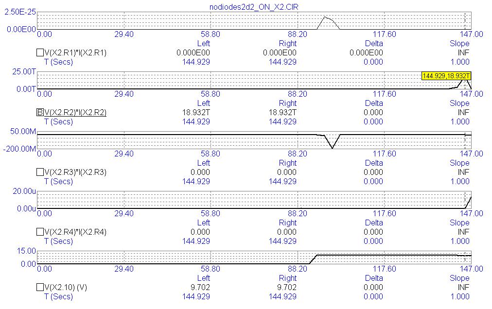
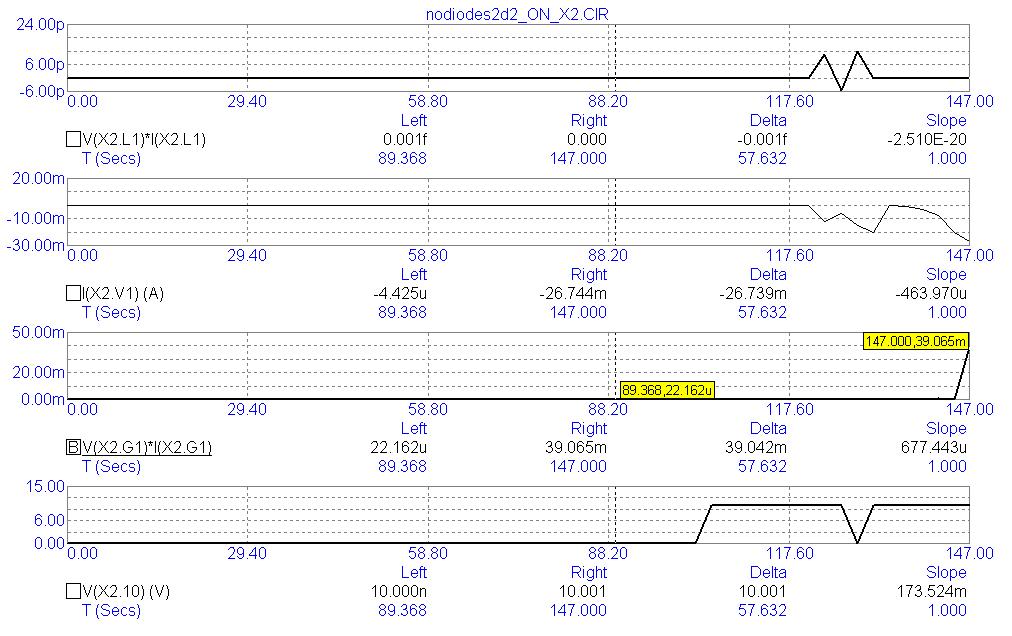
The wattage of the four resistors within the spark gap macro, X2, plus the nodal voltage for node number: X2.10 labeled: "Switchchk"...
|
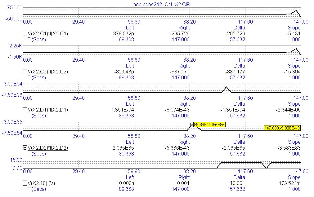
The wattage of capacitors, C1 and C2, plus the wattage of the diodes, D1 and D2, within the spark gap macro, X2. This demonstrates how power is generated and accumulated most of the time. Only occasionally do these components react in the opposite (positive) direction to absorb, convert, and get rid of, this excess energy by spiking in the positive polarity once in a while.
So, causality has not been broken if we examine all of the significant components of a circuit over the entire duration of its run-time!
|
The wattage of the spark gap's electrodes, the amperage of the zero voltage source, and the wattage of the current source for spark gap, X2...
|
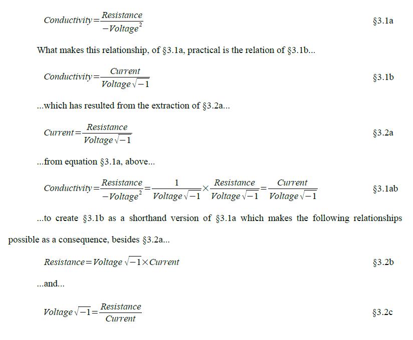
I should close with an implication of this data: super-conduction at room temperature.
Whenever resistance becomes our friend, augmenting the accumulation of a circuit's power-level rather than diminishing it (via its exportation from out of a circuit and into its environment), and whenever the voltage input is so scanty as to appear as if it is non-existent, then Ohm's Law gets multiplicatively inverted whereby the voltage which is squared and which used to be located in the numerator of Ohm's Law is, now, located in its denominator. And the resistance which used to be located in the denominator of Ohm's Law - undermining the output of power by dividing into the square of voltage situated in the numerator of Ohm's Law is, now, located in the numerator. And this multiplicative inversion of Ohm's Law occurs only when the current phase of electrical oscillations is inverted relative to the voltage phase by 180 degrees indicating that one more step of inversion occurs: additive inversion (negation) of Ohm's Law.
But, simulators and electrical engineers don't recognize this multiplicative inversion. They ignore this inversion while admitting (allowing for) its additive inversion. {Or else, I'd never get negative answers for the assessment of power for each component in Micro-Cap (a flavor of Berkeley SPICE).}
This is why Lord Kelvin suggested the word: "mho" as the unit of admittance (conductivity). Instead, the international body in charge of our scientific units of measurement have deemed fit to replace Kelvin's suggestion with the word: "Siemens" and name absolute zero degrees after him as if to discourage our usage of Mho's Law (the inverse of Ohm's Law) and remain sequestered around the notion that only by super-cooling a conductor can any super-conductance be achieved.
Yet, whenever the phase of current is totally inverted relative to the phase of voltage, Ohm's Law no longer applies. Instead, Mho's Law applies and super-conductivity manifests at room temperature.
Viola! Overunity...more energy accumulates inside of a circuit than exits OUT of it putting into doubt whether the Conservation of Energy merely pertains to the conversion of energy, such as: batteries and light bulbs, but does not pertain to its generation and synthesis and accumulation as useless reactive power prior to it becoming useful when converted through a resistor, etc., to alter its negative unity, power factor into a positive unity, power factor.
Here is a similar circuit simulated in LTSPICE...
Schematic...
|
Output and settings...

|