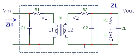
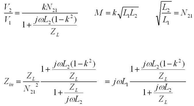
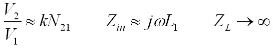
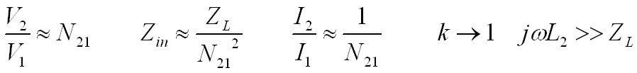
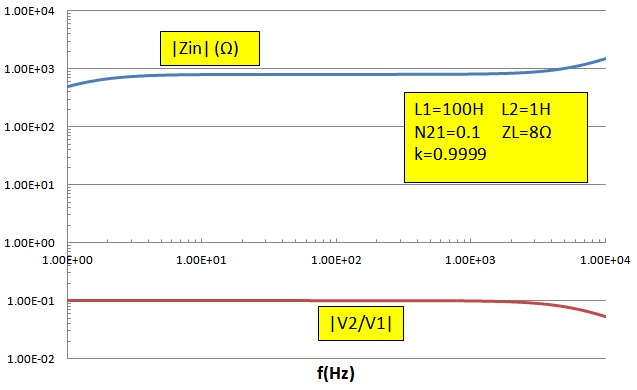
 The calculator below computes the effective complex input impedance Zin and voltage gain V2/V1 using the general expressions
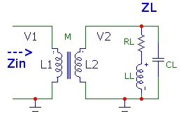
above for an output load ZL consisting of a series resistor and inductor in parallel with a capacitance as shown in the schematic to the right. This type of load
might represent, for example, a simplified model for a loudspeaker connected to a transformer secondary in an audio amplifier circuit with transformer
output coupling. Zin would correspond to the effective (complex) load impedance in the transistor or tube circuit which will determine the circuit gain.The total
output load impedance ZL of these three components is also displayed. The complex quantities are displayed as magnitude and phase.
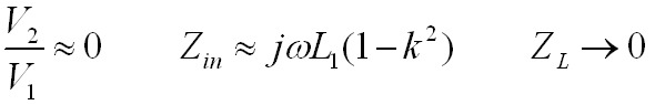
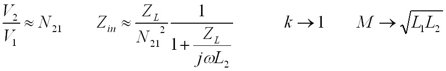
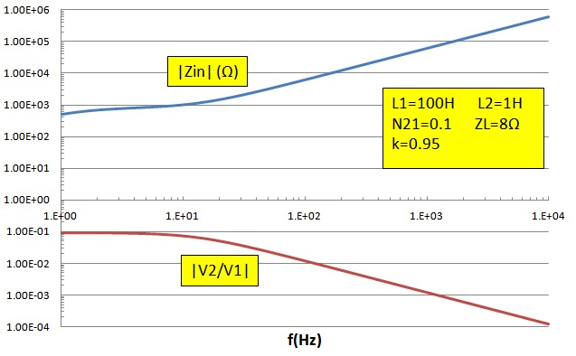
This tool provides assistance with quickly determining the deviation that can be expected
for various transformer loads at any frequency for resistive or reactive secondary loads. It also demonstrates various regimes where the coupling
coefficient can have a strong effect on deviation from ideal transformer behaviour.
The calculator below computes the effective complex input impedance Zin and voltage gain V2/V1 using the general expressions
above for an output load ZL consisting of a series resistor and inductor in parallel with a capacitance as shown in the schematic to the right. This type of load
might represent, for example, a simplified model for a loudspeaker connected to a transformer secondary in an audio amplifier circuit with transformer
output coupling. Zin would correspond to the effective (complex) load impedance in the transistor or tube circuit which will determine the circuit gain.The total
output load impedance ZL of these three components is also displayed. The complex quantities are displayed as magnitude and phase.
This tool provides assistance with quickly determining the deviation that can be expected
for various transformer loads at any frequency for resistive or reactive secondary loads. It also demonstrates various regimes where the coupling
coefficient can have a strong effect on deviation from ideal transformer behaviour.